
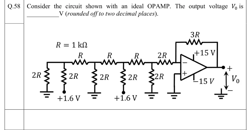
Consider the circuit shown with an ideal OPAMP. The output voltage is ________ V (rounded off to two decimal places).
 Tap to open full size
Figure description
An R-2R resistor ladder drives an inverting op-amp amplifier, with R = 1 k Ω. The top rail of the ladder, from left to right: node A, then a series R to node B, a series R to node C, a series R to node D, and a series 2R to the inverting (−) input of the op-amp. Shunt resistors: node A has two, a 2R to ground (the leftmost resistor) and a 2R to a +1.6 V source. Node B has a 2R to ground. Node C has a 2R to a +1.6 V source. Node D has a 2R to ground. The non-inverting (+) input is grounded. A feedback resistor 3R connects the output to the inverting input. The supply rails are +15 V and -15 V. The output V_0 is measured from the output terminal (+) to ground (−).