
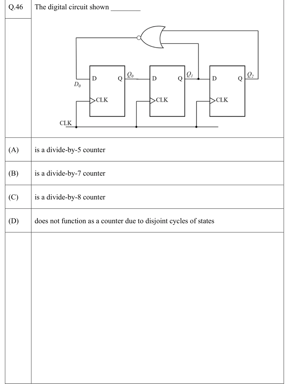
The digital circuit shown ________
 Tap to open full size
Figure description
Three positive-edge-triggered D flip-flops (clock inputs drawn with a triangle, no bubble) share one common clock line CLK. Left to right: FF0 has input D (labelled D_0) and output Q_0; FF1 has D = Q_0 and output Q_1; FF2 has D = Q_1 and output Q_2. So the three flip-flops form a serial shift register Q_0 -> Q_1 -> Q_2. A two-input NOR gate (OR symbol with an output bubble) takes Q_1 (tapped at a junction dot between FF1 and FF2) and Q_2 (fed back from the rightmost output) as inputs; its output is wired back to D_0, the D input of the first flip-flop. There are no other inputs, no preset or clear.
- (A)
is a divide-by-5 counter
- (B)
is a divide-by-7 counter
- (C)
is a divide-by-8 counter
- (D)
does not function as a counter due to disjoint cycles of states