
IAE Academy

GATE 2023 IN Q.41: solution and answer

GATE 2023 · INQ.41 · 2 marks · MCQ

For the given digital circuit, A = B = 1. Assume that AND, OR, and NOT gates have propagation delays of 10 ns, 10 ns, and 5 ns respectively. All lines have zero propagation delay. Given that C = 1 when the circuit is turned on, the frequency of steady-state oscillation of the output Y is ______.
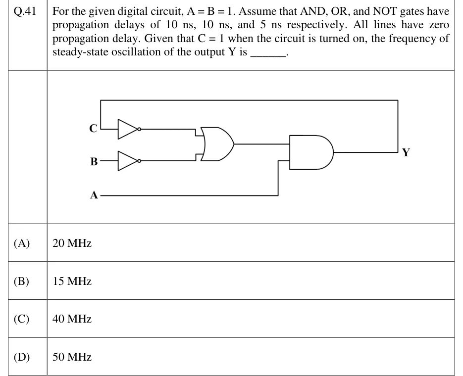
GATE 2023 IN question 41: Combinational loop.Tap to open full size
Figure from the GATE 2023 IN paper. It is part of the question.
Figure description

Combinational loop. Input C goes through a NOT gate to the first input of a 2-input OR gate. Input B goes through a second NOT gate to the second input of the same OR gate. The OR output goes to the first input of a 2-input AND gate; input A goes directly to the second input of the AND gate. The AND output is the output Y, and a wire runs from Y back up and around to the left to become input C (Y is fed back to C).

  1. (A)

    20 MHz

  2. (B)

    15 MHz

  3. (C)

    40 MHz

  4. (D)

    50 MHz

Answer and solution

ANSWER

With the circuit becomes with : a single inversion around a loop whose delay is . The period is , so the output oscillates at , option (A).

Official answer: ASource: Official answer key, GATE 2023 IN (IIT Kanpur)

  1. Write the logic. With meaning complement: . The feedback wire from the output back to the input makes .

  2. Put in the constants . Then , so the OR gate passes straight through (). Because , the AND gate passes the OR output straight through (). So , but only after a delay.

  3. Since , the closed path contains exactly one inversion. That makes it a ring oscillator: no stable state is possible, because has no solution. So keeps toggling.

  4. Delay once around the loop, through NOT, then OR, then AND: . The NOT gate on is not in the loop, because is a constant and that gate's output never changes.

  5. Trace from at . The NOT output falls to 0 at , the OR output at , and at . That new 0 goes round again: the NOT output rises to 1 at , the OR output at , and at . So stays at each level for . How the gates power up can affect the first few nanoseconds, but not the steady-state period.

  6. In an inverting loop, the output needs one trip round the loop to go from 1 to 0 and a second trip to go back to 1. So the period is twice the loop delay: .

  7. This is option (A).

KEY IDEA

A closed loop with an odd number of inversions is a ring oscillator. Its period is twice the total propagation delay round the loop, and only gates whose inputs actually change count towards that delay. Here the constant inputs A and B make the OR and AND gates act as plain delays, so the loop is effectively one inverter plus 20 ns of extra delay.

WATCH OUT FOR

Taking the period as a single trip round the loop gives and 40 MHz (option C). You need two trips, one for each edge. Counting only the OR and AND delays and missing the NOT gate in the loop gives , which students often misread as the period and so pick 50 MHz (option D). Adding the NOT gate on is also wrong: is constant, so that gate is not in the loop.

From the GATE 2023 IN paper. Every question of this paper · Download the full paper · All 30 Sequential questions, with notes

More Sequential questions