
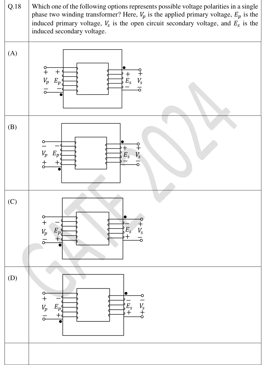
Which one of the following options represents possible voltage polarities in a single phase two winding transformer? Here, is the applied primary voltage, is the induced primary voltage, is the open circuit secondary voltage, and is the induced secondary voltage.
 Tap to open full size
Figure description
Each option (A)-(D) shows the same core transformer schematic: two windings on a common rectangular core, primary winding on the left with two external terminals (top and bottom, each shown as a small circle 'o'), secondary winding on the right likewise with top and bottom terminals. In every option the dot (filled circle '•') mark on the primary is at its BOTTOM terminal (next to the label E_p) and the dot on the secondary is at its TOP terminal (next to the label E_s) — dot placement is identical in all four options; only the +/- polarity labels differ. Labels read outward from the winding: primary column order (left to right) is V_p terminal, then E_p terminal (winding lead); secondary column order is E_s terminal (winding lead) then V_s terminal. Polarity signs per option, top/bottom: (A) top: V_p+,E_p+; bottom(dot): V_p-,E_p- | top(dot): E_s+,V_s+; bottom: E_s-,V_s-. (B) top: V_p-,E_p-; bottom(dot): V_p+,E_p+ | top(dot): E_s+,V_s+; bottom: E_s-,V_s-. (C) top: V_p+,E_p-; bottom(dot): V_p-,E_p+ | top(dot): E_s-,V_s+; bottom: E_s+,V_s-. (D) top: V_p+,E_p-; bottom(dot): V_p-,E_p+ | top(dot): E_s-,V_s-; bottom: E_s+,V_s+.
- (A)
Figure — polarities as listed above for (A)
- (B)
Figure — polarities as listed above for (B)
- (C)
Figure — polarities as listed above for (C)
- (D)
Figure — polarities as listed above for (D)