
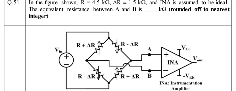
In the figure shown, , , and INA is assumed to be ideal. The equivalent resistance between A and B is ____ (rounded off to nearest integer).
 Tap to open full size
Figure description
A four-arm resistive bridge drawn as a diamond, with top node T, bottom node Bot, left node L and right node Rt. Every arm is a variable resistor (a zig-zag crossed by a vertical arrow, like a strain gauge). The arrow points up on the R + ΔR arms and down on the R - ΔR arms. Arm T-L: R + ΔR. Arm T-Rt: R - ΔR. Arm L-Bot: R - ΔR. Arm Rt-Bot: R + ΔR. A voltage source V_in on the left has its + terminal on top. Its + terminal is wired to the top node T and its - terminal to the bottom node Bot, so V_in is applied across T-Bot. The right node Rt is wired to terminal A. The left node L is wired to terminal B by a wire that runs right, steps down, and passes over the lead of the lower-right arm through a crossover arc (not a junction) before stepping down to B. A goes to the + (non-inverting) input of an instrumentation amplifier labelled INA, and B goes to its - (inverting) input. The INA has supply rails V_CC (top) and -V_EE (bottom) and output V_out. Caption: 'INA: Instrumentation Amplifier'.