
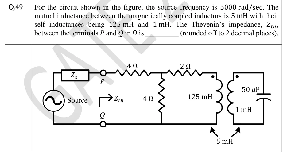
For the circuit shown in the figure, the source frequency is 5000 rad/sec. The mutual inductance between the magnetically coupled inductors is 5 mH with their self inductances being 125 mH and 1 mH. The Thevenin's impedance, , between the terminals and in is ________ (rounded off to 2 decimal places).
 Tap to open full size
Figure description
An AC voltage source, labelled 'Source', sits on the far left. Its top terminal goes through a series impedance Z_s to terminal P. Its bottom terminal goes to terminal Q. P and Q are open terminals, and an arrow labelled Z_th points to the right from them, into the network. From P a series 4 Ω resistor leads to a node A. A shunt 4 Ω resistor connects node A to the bottom rail, which is the Q line. From node A a series 2 Ω resistor leads to the top of a 125 mH inductor, the primary, whose other end goes to the bottom rail. The primary has its dot at the top. The primary is magnetically coupled, with M = 5 mH shown by arrows at the bottom, to a 1 mH secondary inductor, also dotted at the top. The secondary sits in its own isolated loop in series with a 50 capacitor. The secondary loop has no conductive connection to the rest of the circuit.