
IAE Academy

GATE 2018 IN Q.52: solution and answer

GATE 2018 · INQ.52 · 2 marks · NAT

Assuming ideal opamp, the RMS voltage (in mV) in the output only due to the 230 V, 50 Hz interference is (up to one decimal place) ______.
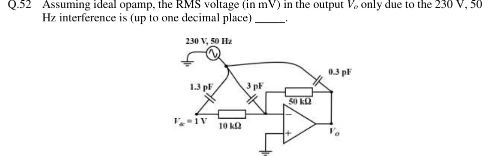
GATE 2018 IN question 52: An inverting amplifier.Tap to open full size
Figure from the GATE 2018 IN paper. It is part of the question.
Figure description

An inverting amplifier. A dc source V_dc = 1 V drives a 10 k Ω resistor whose other end is the op-amp inverting (−) input. A 50 k Ω feedback resistor connects the inverting input to the output V_o. The non-inverting (+) input is grounded. An interference source, 230 V, 50 Hz, has one terminal grounded; its other terminal goes to a single node from which three stray capacitors branch: 1.3 pF to the V_dc node (left end of the 10 k Ω resistor), 3 pF to the inverting-input node (the junction of the 10 k Ω and 50 k Ω resistors), and 0.3 pF to the output node V_o.

Answer and solution

ANSWER

The 50 Hz interference produces about 10.8 mV rms at the output ().

Official answer: 10.6 to 11.0Source: Official answer key, GATE 2018 IN (IIT Guwahati)

  1. Assumptions: the op-amp is ideal (infinite gain, no input current, zero output impedance), and is an ideal dc source. The circuit is linear, so use superposition. Switch off , which only sets a dc output of , and keep only the 50 Hz source, rms, .

  2. 1.3 pF capacitor: it ends on the node of the ideal voltage source . For ac that node is shorted to ground, so the current in this capacitor flows into the source and never reaches the amplifier. It adds nothing to .

  3. 0.3 pF capacitor: it ends on the output of an ideal op-amp, which acts as a voltage source with zero output impedance. Current injected there cannot change , so it adds nothing either.

  4. 3 pF capacitor: it ends on the inverting input. The (+) input is grounded, so the virtual short holds this node at exactly and the whole source voltage appears across the 3 pF capacitor:

  5. KCL at the inverting node: the ideal op-amp draws no input current. With switched off, both ends of the resistor are at , so it carries no current. All of therefore flows through the feedback resistor:

  6. Output magnitude:

KEY IDEA

Only a stray capacitance that ends on a high-impedance node lets interference through. The inverting input of an ideal op-amp is a virtual ground, so the 3 pF capacitor passes a current that must all flow through . Capacitors that end on low-impedance nodes (the ideal dc source, or the op-amp output) send their current into those sources and have no effect on .

WATCH OUT FOR

Adding all three capacitances (4.6 pF) and getting about 16.6 mV. The 1.3 pF current goes into the ideal dc source and the 0.3 pF current goes into the zero-impedance op-amp output, so neither reaches . Other slips: treating the 1.3 pF current as an input through the 10 kΩ resistor with gain , or forgetting that the answer is asked for in mV.

From the GATE 2018 IN paper. Every question of this paper · Download the full paper · All 2 Noise & shielding (IN) questions, with notes