
IAE Academy

GATE 2024 IN Q.56: solution and answer

GATE 2024 · INQ.56 · 2 marks · NAT

A shielded cable with and is used to connect the inductive sensors as shown in the figure. The RMS value of is ____ V (rounded off to two decimal places).

Note: Assume all components are ideal, and sensors are not magnetically coupled.
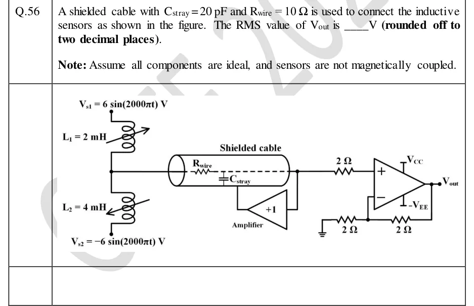
GATE 2024 IN question 56: Two variable inductors (inductive sensors, each drawn with a diagonal arrow) are in series.Tap to open full size
Figure from the GATE 2024 IN paper. It is part of the question.
Figure description

Two variable inductors (inductive sensors, each drawn with a diagonal arrow) are in series. The top end of L_1 = 2 mH goes to source V_s1 = 6 sin (2000 π t) V. The bottom end of L_2 = 4 mH goes to source V_s2 = -6 sin (2000 π t) V. The junction of L_1 and L_2 enters a shielded cable, drawn as a cylinder labelled 'Shielded cable'. The inner wire is a dashed line along the cable axis. It has a series resistance R_wire near its input end, and a capacitor C_stray is drawn from the inner wire to the shield. At the far end of the cable the wire meets a node. That node feeds (a) the input of a unity-gain buffer ('+1', labelled 'Amplifier'), drawn pointing left, whose output runs up to the cable shield (driven shield / guard), and (b) a 2 Ω resistor into the non-inverting (+) input of an op-amp powered from V_CC and -V_EE. The op-amp is wired as a non-inverting amplifier: a 2 Ω resistor from the output V_out to the inverting (−) input, and a 2 Ω resistor from the inverting input to ground.

Answer and solution

ANSWER

, so .

Official answer: 2.81 to 2.85Source: Official answer key, GATE 2024 IN (IISc Bengaluru)

  1. What the guard does. The unity-gain buffer copies the voltage of the cable's inner wire onto the shield, so both plates of sit at the same potential. With zero voltage across it, carries no current and has no effect on the signal. This is a driven shield. (Even without the guard its effect would be negligible here. At , , while the sensor divider's Thevenin impedance is only .)

  2. The cable draws no current. An ideal op-amp input and an ideal buffer input draw zero current, and carries none. So no current flows in or in the input resistor. Both drop , and the + input sits at the sensor junction voltage .

  3. The sensors form an unloaded inductive divider. and carry the same current and are not magnetically coupled, so each has impedance with (). The two sources are in phase (one is the negative of the other), so the factors cancel and the divider acts on the amplitudes directly.

  4. Superposition (Millman's theorem) at the junction:

  5. Check with KVL: . The drop across has amplitude , so (amplitude). This agrees with the previous step.

  6. Non-inverting amplifier gain. Assume an ideal op-amp (virtual short between the inputs, no input current) and an output that stays inside the supply rails:

  7. Output:

  8. RMS value:

KEY IDEA

The buffer holds the shield at the inner wire's voltage, so has no voltage across it and carries no current. The ideal amplifier inputs draw no current either, so and the input resistor drop nothing. The op-amp therefore sees the unloaded inductive-divider voltage . A non-inverting gain of 2 makes the peak 4 V, and RMS.

WATCH OUT FOR

Swapping the divider weights. The junction voltage weights by the FAR inductor , not by . Writing gives , which has the same magnitude only by coincidence, so check the sign with KVL. Other slips: using an inverting gain of instead of the non-inverting (answer ); loading the divider with , the resistor or even though no current flows; and reporting the peak (4 V) instead of the RMS value.

From the GATE 2024 IN paper. Every question of this paper · Download the full paper · All 2 Noise & shielding (IN) questions, with notes