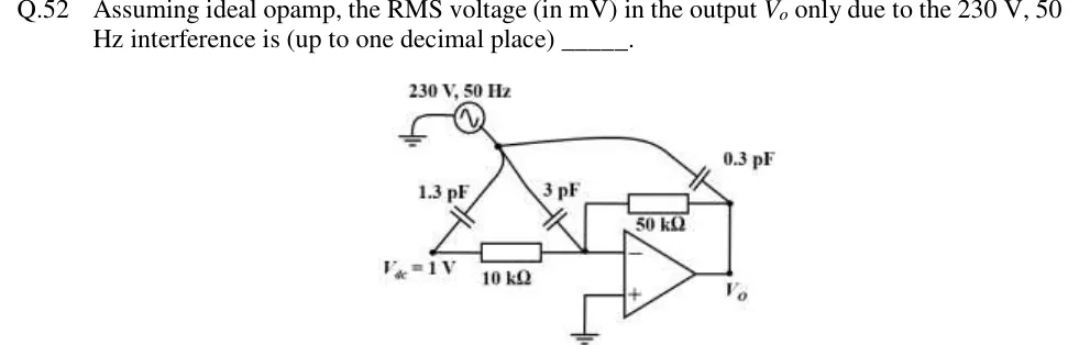
An electrostatic shield is a conducting enclosure (foil, braid, metal box) around the victim that intercepts the electric field lines from the source. The field now ends on the shield, and the coupling capacitance from source to victim falls almost to zero. The shield works only when it is connected to the victim circuit's reference (ground or common). A floating shield simply couples the source to the victim through two capacitors in series and can make matters worse. Any length of victim conductor sticking out beyond the shield, and any gap in the shield, still couples.
Magnetic fields are much harder to shield. At low frequencies (50 Hz and its harmonics) a non-magnetic conductor such as copper or aluminium does almost nothing, because its skin depth is several millimetres; a high-permeability material (mu-metal, silicon steel) is needed to divert the flux around the victim. At high frequencies a good conductor shields well: the field induces eddy currents whose own field opposes it, and the wave is absorbed within a few skin depths. In a coaxial cable grounded at both ends, above about five times the shield cut-off frequency fsh=Rsh/(2πLsh) (shield resistance and inductance), the return current flows on the shield rather than through ground; the go and return currents are then coaxial, the loop area is tiny, and magnetic coupling in both directions is small.
Twisted pair. Twisting the signal and return conductors divides the loop into many small loops of alternating orientation. A uniform external field induces equal and opposite voltages in adjacent twists, which cancel, so the net induced voltage is small; the tighter the twist, the better. This works only when the whole return current flows in the return conductor, that is, when the circuit is grounded at one end only; if it is grounded at both ends, part of the return current flows through the ground loop, whose area twisting does not reduce. Twisting also reduces the field the pair itself radiates. It gives little protection against capacitive coupling, so a shield is added for that (shielded twisted pair). Driving the pair from a balanced source into a differential receiver also cancels capacitive pickup that reaches both wires equally.
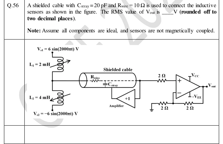
Guard ring. On a board, a high-impedance node (an electrometer or photodiode amplifier input) collects leakage current across the board surface from nearby traces at other potentials. A guard ring is a copper track surrounding the node, held at (nearly) the node's own potential by a low-impedance point in the circuit: the inverting-input potential for a non-inverting amplifier or follower, or ground for an inverting amplifier whose inverting input sits at virtual ground. With no voltage across the gap, no leakage flows into the node; leakage from other traces is intercepted by the guard and returned to a low-impedance point. A driven shield on a cable applies the same idea to cable leakage and capacitance.
A ground is the reference against which voltages are measured and the path by which currents return. Real ground conductors have resistance and inductance, so two ground points generally differ in potential whenever current flows. Keep three purposes apart: safety ground (the enclosure bonded to earth so that a fault cannot leave it live), signal ground (the reference for low-level signals) and power or noisy ground (returns of motors, relays, digital logic and high-current stages). Separate returns for these, joined at a single point, avoid common-impedance coupling between them. Never remove a safety earth to cure noise.
Ground loops. When a signal circuit is grounded at two points, say a grounded sensor at one end and a grounded amplifier at the other, the signal return and the ground path form a closed loop. Any potential difference VG between the two ground points, and any magnetic flux linking the loop, drives a current around it, and part of the resulting voltage appears in series with the signal, typically as 50 Hz hum. Ground loops matter most at low frequency and with low-level signals.
Normal-mode and common-mode interference. Normal-mode (series-mode, differential-mode) interference appears in series with the signal, between the two input leads, so the input stage cannot tell it apart from the signal: it has to be removed by filtering or by the conversion method. Common-mode interference appears equally on both input leads with respect to ground (a ground-potential difference is the usual source) and is rejected by a differential input according to its CMRR. Unequal lead or source impedances convert part of a common-mode voltage into a normal-mode one.
NORMAL-MODE REJECTION OF AN INTEGRATING ADC
An integrating (for example dual-slope) ADC averages its input over the integration time T, so a normal-mode sinusoid at frequency f is attenuated by this factor. It is ideally infinite when T is a whole number of periods of the interference: T=20 ms, or any multiple of it, rejects 50 Hz and all its harmonics. NMRRdB=20log10NMRR.

 Tap to open full size