
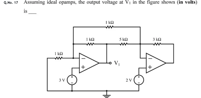
Assuming ideal opamps, the output voltage at in the figure shown (in volts) is ____
 Tap to open full size
Figure description
Two op-amps. LEFT op-amp: inverting input (−) on top, non-inverting input (+) below; its output is the node labelled V1. The (+) input goes to the positive terminal of a 3 V source whose negative terminal is on the bottom ground rail. The (−) input connects to node A. Node A has three branches: (i) a 1 kΩ resistor going left, whose far end drops down to the bottom ground rail; (ii) a 1 kΩ resistor (middle row) going right to the V1 node (V1 connects up to this row); (iii) a 1 kΩ resistor along the top row going right to node B. From the V1 node, a 5 kΩ resistor (middle row) also goes right to node B. RIGHT op-amp: inverting input (−) on top, non-inverting input (+) below. Its (−) input is node B; its (+) input goes to the positive terminal of a 2 V source whose negative terminal is on the ground rail. Its output loops back up and through a 3 kΩ resistor to node B. The bottom rail carries the ground symbol and ties together the far end of the left 1 kΩ and the negative terminals of both sources.