
IAE Academy

GATE 2020 CS Q.4: solution and answer

GATE 2020 · CSQ.4 · 1 mark · MCQ

Consider the following data path diagram.

Consider an instruction: R0 ← R1 + R2. The following steps are used to execute it over the given data path. Assume that PC is incremented appropriately. The subscripts r and w indicate read and write operations, respectively.

1. R2r, TEMP1r, ALUadd, TEMP2w
2. R1r, TEMP1w
3. PCr, MARw, MEMr
4. TEMP2r, R0w
5. MDRr, IRw

Which one of the following is the correct order of execution of the above steps?
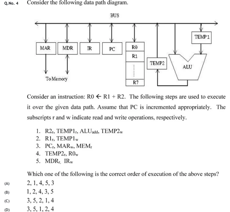
GATE 2020 CS question 4: A single-bus datapath diagram.Tap to open full size
Figure from the GATE 2020 CS paper. It is part of the question.
Figure description

A single-bus datapath diagram. A horizontal line labeled BUS runs across the top with double-headed (bidirectional) arrows connecting down to each block below it. From left to right, the blocks connected to the bus are: MAR (with a separate downward arrow labeled 'To Memory'), MDR (also connected 'To Memory' via the same downward line as MAR), IR, PC, a register file block containing R0, R1, R2,... (dots), R7 (i.e., R0 through R7 stacked vertically), TEMP2, and a V-shaped ALU block. Above and to the right, TEMP1 sits above the ALU and also connects down to the ALU. TEMP2 feeds into the left input of the ALU (via a line from TEMP2 down and into the ALU), and the ALU's output line loops back up into TEMP2's input from below/right (TEMP2's box has an arrow both up to bus and a feed line to ALU's left side coming from below). TEMP1 connects down into the ALU's right input. The ALU (V-shaped) output goes up to TEMP1's block position at top right. MAR and MDR each have an additional downward arrow labeled 'To Memory'.

  1. (A)

    2, 1, 4, 5, 3

  2. (B)

    1, 2, 4, 3, 5

  3. (C)

    3, 5, 2, 1, 4

  4. (D)

    3, 5, 1, 2, 4

Answer and solution

ANSWER

The correct order of execution is 3, 5, 2, 1, 4 — option (C).

Official answer: CSource: Official answer key, GATE 2020 CS (IIT Delhi)

  1. Fetch phase: step 3 (PCr, MARw, MEMr) sends PC to MAR and starts a memory read; step 5 (MDRr, IRw) moves the fetched word from MDR into IR only once that read has completed. Hence step 3 must precede step 5, which already rules out options (A) and (B).

  2. Execute phase for R0 ← R1 + R2: the ALU takes one operand directly off the bus and the other from the latched register TEMP1.

  3. Step 2 (R1r, TEMP1w) places R1 on the bus and latches it into TEMP1.

  4. Step 1 (R2r, TEMP1r, ALUadd, TEMP2w) places R2 on the bus while TEMP1 supplies its latched value to the ALU; ALUadd computes bus + TEMP1 and latches the sum into TEMP2. For this sum to be R1 + R2, TEMP1 must already hold R1, so step 2 must execute before step 1 — this rules out option (D).

  5. Step 4 (TEMP2r, R0w) drives the ALU result held in TEMP2 onto the bus and writes it into R0, so it must be the last step, after TEMP2 has been loaded by step 1.

  6. Assembling: fetch (3, 5) then execute (2, 1, 4) gives 3, 5, 2, 1, 4 — option (C).

KEY IDEA

In this single-bus datapath, the ALU has two inputs: one comes directly (combinationally) off the bus, the other from the latched register TEMP1. So whichever step places a value into TEMP1 must execute before the step that uses TEMP1 as an ALU input. Similarly, a memory read (MEMr) takes time to complete, so the step that issues it must finish before the step that consumes its result from MDR.

WATCH OUT FOR

Assuming the four steps that don't obviously belong to "fetch" (1, 2, 4) can be freely reordered as long as they come after the fetch pair, and picking option (D) by reading step 1 before step 2 in numeric order — without checking that step 1 needs TEMP1 to already hold R1, which only step 2 provides.

From the GATE 2020 CS paper. Every question of this paper · Download the full paper · All 5 ALU & control unit questions, with notes

More ALU & control unit questions