
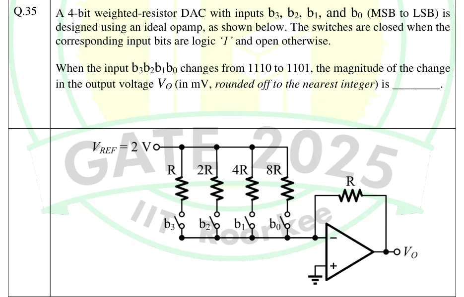
A 4-bit weighted-resistor DAC with inputs , , , and (MSB to LSB) is designed using an ideal opamp, as shown below. The switches are closed when the corresponding input bits are logic '1' and open otherwise.
When the input changes from 1110 to 1101, the magnitude of the change in the output voltage (in mV, rounded off to the nearest integer) is ________.
 Tap to open full size
Figure description
A reference source V_REF = 2 V drives a common top rail. Four resistors hang from this rail in parallel, from left to right: R, 2R, 4R, 8R. Each resistor's lower end goes through a single-pole switch labelled, left to right, b_3, b_2, b_1, b_0 (so b_3 is in series with R, b_2 with 2R, b_1 with 4R, b_0 with 8R). The far sides of all four switches join a common bottom node, which connects to the inverting (−) input of an ideal op-amp. A feedback resistor R runs from the op-amp output back to the inverting input. The non-inverting (+) input is grounded. The output is labelled V_O.