
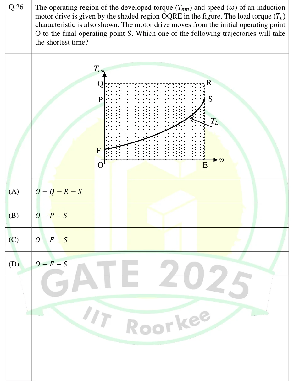
The operating region of the developed torque () and speed () of an induction motor drive is given by the shaded region OQRE in the figure. The load torque () characteristic is also shown. The motor drive moves from the initial operating point O to the final operating point S. Which one of the following trajectories will take the shortest time?
 Tap to open full size
Figure description
A T_em (vertical axis) vs ω (horizontal axis) plot, origin at O. A shaded (dotted) rectangular region OQRE is bounded by: the vertical axis from O to Q (torque axis, at ω =0), the horizontal top line from Q to R (at torque level T_Q, the maximum torque), the vertical line from R down to E (at speed ω_E, the maximum speed shown), and the horizontal axis from E back to O. Point P lies on the vertical torque axis (segment OQ) below Q, marking an intermediate torque level; a dashed horizontal line runs from P across to point S. Point F lies on the vertical torque axis below P, near the bottom, marking a lower/starting torque level. A smooth monotonically increasing curve, labelled T_L (the load torque characteristic), starts at point F (on the torque axis, ω =0) and rises with increasing slope (convex, fan/quadratic-like shape) as ω increases, passing below Q and R, and terminating at point S, which lies at the top-right of the shaded region directly below R (i.e., S is at ω = ω_E, at a torque level equal to that of the dashed line from P — below T_Q). The four candidate trajectories from O to S are drawn as straight-line paths: O to Q to R to S (up the torque axis, across the top, then down to S); O to P to S (up the torque axis to P, then diagonally to S); O to E to S (along the speed axis to E, then straight up to S); O to F to S (up the torque axis to F, then along/near the T_L curve to S).
- (A)
- (B)
- (C)
- (D)