
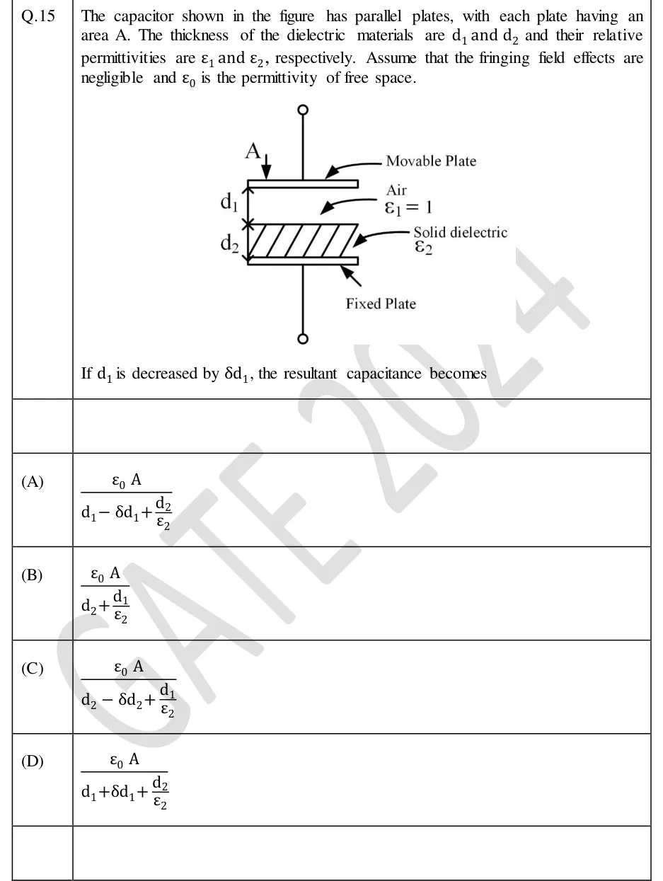
The capacitor shown in the figure has parallel plates, with each plate having an area A. The thickness of the dielectric materials are and and their relative permittivities are and , respectively. Assume that the fringing field effects are negligible and is the permittivity of free space.
[Figure]
If is decreased by , the resultant capacitance becomes
 Tap to open full size
Figure description
A parallel-plate capacitor drawn with its plates horizontal. A vertical lead with a small open-circle terminal at the top connects to the upper plate, labelled 'Movable Plate'; an arrow marked 'A' points down onto the upper plate (the plate area). Directly below the upper plate is an air gap of thickness d_1 (dimension arrow on the left), labelled 'Air, ε_1 = 1'. Below the air gap is a hatched slab of thickness d_2 (dimension arrow on the left), labelled 'Solid dielectric ε_2', which rests directly on the lower plate, labelled 'Fixed Plate'. A vertical lead runs from the lower plate down to a second open-circle terminal. The two layers are stacked one above the other, so each fills the full plate area and they lie in series between the plates.
- (A)
- (B)
- (C)
- (D)