
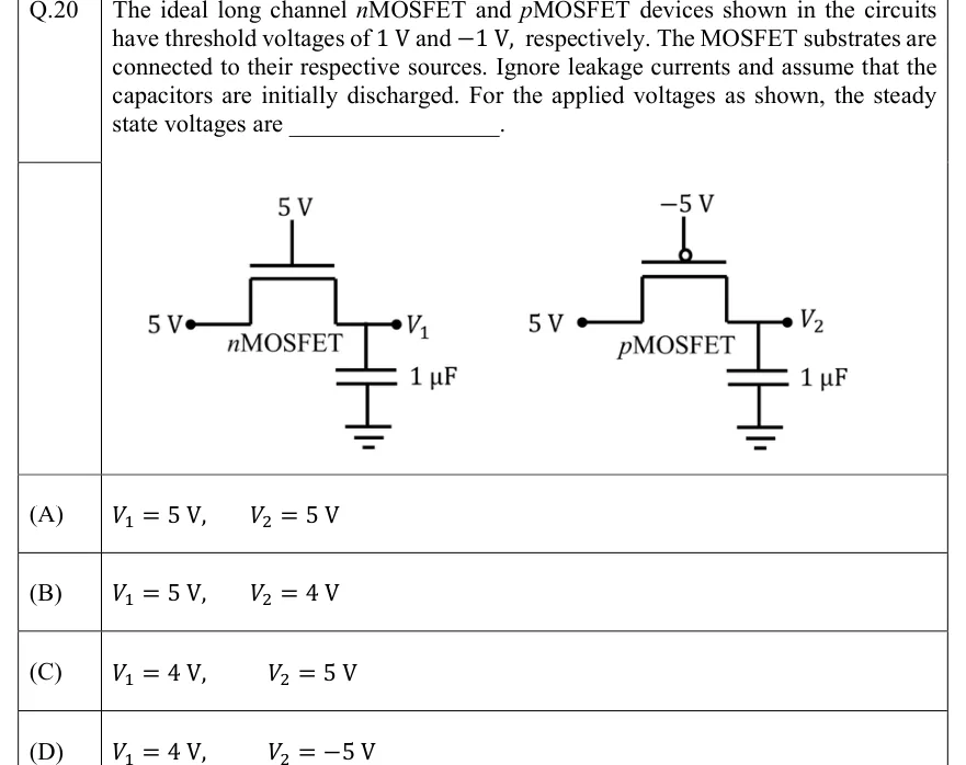
The ideal long channel MOSFET and MOSFET devices shown in the circuits have threshold voltages of 1 V and V, respectively. The MOSFET substrates are connected to their respective sources. Ignore leakage currents and assume that the capacitors are initially discharged. For the applied voltages as shown, the steady state voltages are ____________.
 Tap to open full size
Figure description
Two separate circuits side by side. LEFT circuit: an nMOSFET with its gate connected to a 5 V supply (gate terminal at top), its source (left terminal) connected to a '5 V' node, and its drain (right terminal) connected to node V1; a 1 uF capacitor connects node V1 to ground. RIGHT circuit: a pMOSFET with its gate connected to a '-5 V' supply (gate terminal at top, with a small circle indicating the PMOS gate bubble), its source (left terminal) connected to a '5 V' node, and its drain (right terminal) connected to node V2; a 1 uF capacitor connects node V2 to ground.
- (A)
V1 = 5 V, V2 = 5 V
- (B)
V1 = 5 V, V2 = 4 V
- (C)
V1 = 4 V, V2 = 5 V
- (D)
V1 = 4 V, V2 = -5 V