
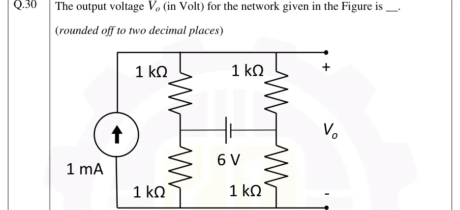
The output voltage (in Volt) for the network given in the Figure is ____. (rounded off to two decimal places)
 Tap to open full size
Figure description
Four nodes: top rail T, bottom rail G, and two middle nodes A (left) and B (right). A 1 mA independent current source sits on the far left between G and T, with its arrow pointing up (current driven from the bottom rail into the top rail). A continuous top wire joins the source's upper terminal, the top of the left resistor column, the top of the right resistor column and the output terminal marked +. A continuous bottom wire joins the source's lower terminal, the bottoms of both columns and the output terminal marked -. Left column: a 1 kΩ resistor from T down to node A, then a 1 kΩ resistor from A down to G. Right column: a 1 kΩ resistor from T down to node B, then a 1 kΩ resistor from B down to G. A 6 V battery is connected horizontally between A and B. Its long plate (positive terminal) faces A and its short plate (negative terminal) faces B, so V_A - V_B = 6 V. V_o is the voltage between the top rail (+) and the bottom rail (-).