
IAE Academy

GATE 2025 IN Q.63: solution and answer

GATE 2025 · INQ.63 · 2 marks · NAT

In the circuit shown, the switch is opened at s. The current at ms is ________ mA (rounded off to two decimal places).
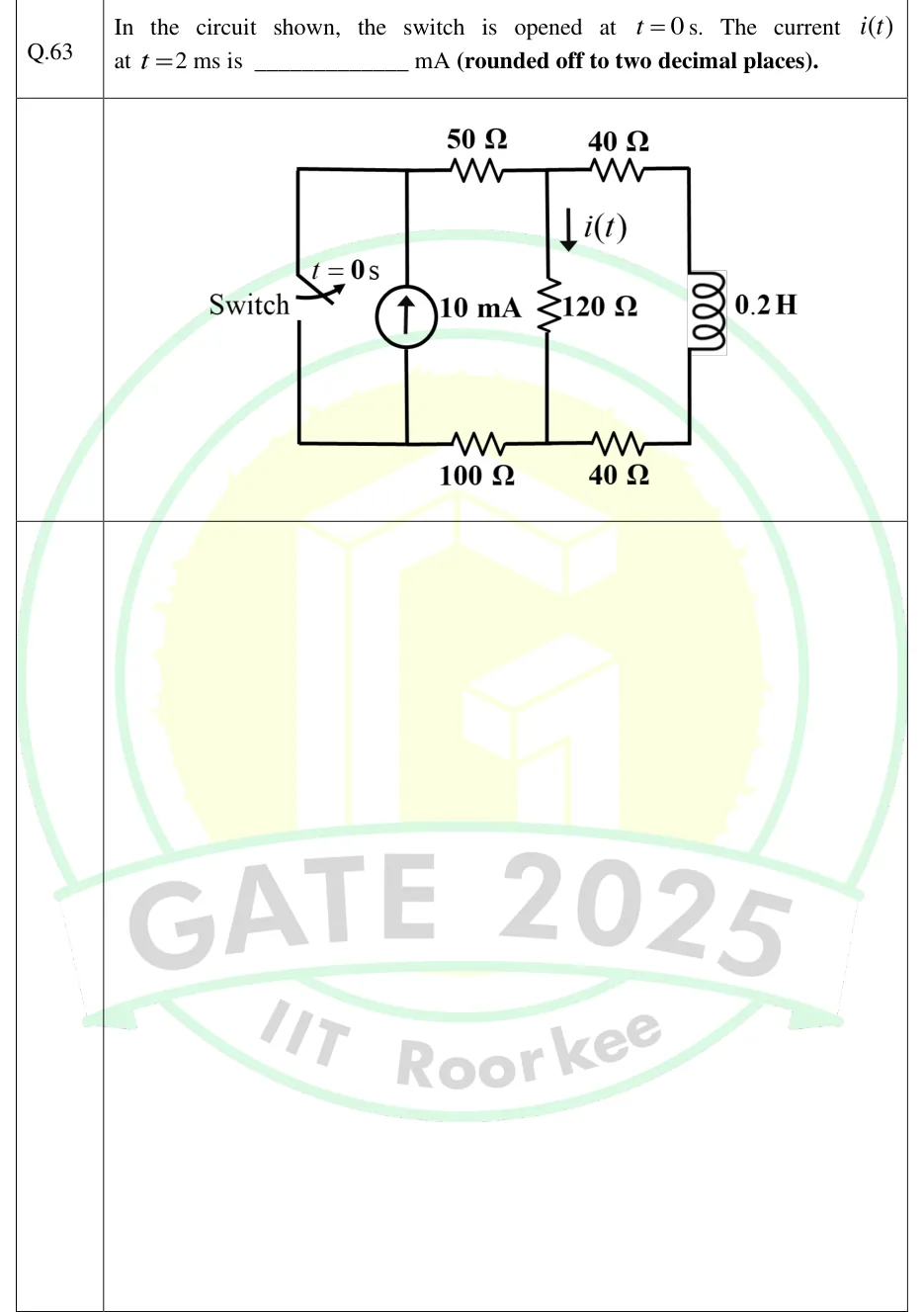
GATE 2025 IN question 63: A ladder-type circuit.Tap to open full size
Figure from the GATE 2025 IN paper. It is part of the question.
Figure description

A ladder-type circuit. The nodes are not labelled in the figure; the letters here are for reference only: A top-left, B top-middle, D top-right, E bottom-right, C bottom-middle, F bottom-left. Leftmost vertical branch: a switch between A (top) and F (bottom), labelled 'Switch' and 't = 0 s'. It is closed for t < 0 and opens at t = 0. Next vertical branch, also between A and F: an independent 10 mA current source with its arrow pointing up, so it drives current from F into A. Top rail: a 50 Ω resistor from A to B, then a 40 Ω resistor from B to D. Middle vertical branch: a 120 Ω resistor from B down to C. It carries the current i(t), shown by a downward arrow (B to C). Rightmost vertical branch: a 0.2 H inductor from D down to E. Bottom rail: a 40 Ω resistor from E to C, then a 100 Ω resistor from C to F.

Answer and solution

ANSWER

.

Official answer: 4.60 to 5.00Source: Official answer key, GATE 2025 IN (IIT Roorkee)

  1. Before the switch opens (): the closed switch shorts the 10 mA source, so all of the source current flows through the switch. No source drives the rest of the network, so in steady state every current in it is zero: .

  2. Continuity of inductor current: , so the inductor acts as an open circuit at .

  3. Circuit for : with the switch open, the 10 mA source is in series with the 50 Ω and 100 Ω resistors. An ideal current source fixes the current in its series path, so these two resistors do not affect the split: exactly 10 mA enters node B and leaves node C. Between B and C there are two parallel paths: the 120 Ω resistor, and the series path .

  4. Initial value: since , all of the 10 mA goes through the 120 Ω resistor, so .

  5. Final value (inductor as a short circuit, current division):

  6. Time constant: open-circuit the current source and find the resistance the inductor sees. The 50 Ω and 100 Ω resistors are left on an open branch and drop out, so and

  7. First-order response: Check: the inductor current is , and KCL at node B gives , the same expression.

  8. At :

KEY IDEA

When the switch opens, the ideal 10 mA source is forced to drive a single RL network. The 50 Ω and 100 Ω resistors in series with the source affect neither how the current splits nor the time constant. The current splits between 120 Ω and the path 40 Ω + L + 40 Ω: all of it goes through 120 Ω at , because the inductor starts with zero current, and it settles to the resistive current-division value. The inductor sees , so .

WATCH OUT FOR

Counting the 50 Ω and 100 Ω resistors in the time constant (e.g. ), or shorting the current source instead of opening it when finding . Opening the source leaves those resistors on an open branch, so they drop out. Another slip is taking by treating the 120 Ω resistor's current as continuous. Only the inductor current is continuous; the resistor current jumps from 0 to 10 mA at .

From the GATE 2025 IN paper. Every question of this paper · Download the full paper · All 20 Transients questions, with notes

More Transients questions