IAE Academy

GATE EC · EE · IN

Transients in RL, RC and RLC circuits

Transient analysis finds how the voltages and currents of a circuit with inductors and capacitors move from one steady state to another after a switch operates or a source is applied. A typical transient problem comes down to three steps. First, fix the initial conditions at from the continuity of capacitor voltage and inductor current. Second, find the final (or sinusoidal steady-state) value. Third, join the two through the circuit's natural response: a single time constant for a first-order circuit, or the roots of for a second-order one.

20 previous-year questions · 20 solved · 5 practice questions

Initial conditions: just before and just after switching

Conventions in these notes. A switch operates at . The instant is just before it operates (the old circuit, usually in DC steady state), and is just after (the new circuit). Each element follows the passive sign convention: the reference current enters the terminal marked + for the reference voltage, so and . Sinusoidal amplitudes in these notes are peak values, not rms.

The energy stored in a capacitor, , and in an inductor, , cannot change in zero time unless infinite power is available. So as long as the capacitor current and the inductor voltage stay finite (no impulses), the capacitor voltage and the inductor current are continuous. Everything else can jump at the switching instant, including , and every resistor voltage and current.

CONTINUITY OF THE STATE VARIABLES

Holds whenever and contain no impulse. It can fail in two ways: a source that itself contains an impulse (such as ), or a switching that creates a loop of capacitors and ideal voltage sources whose voltages do not already satisfy KVL, or a cut-set of inductors and ideal current sources whose currents do not already satisfy KCL (see the tip below). Put in terms of charge and flux linkage: and are continuous.

Element

At

In DC steady state (, or after a long time)

Resistor

Resistor (its and may jump)

Resistor

Capacitor,

Short circuit

Open circuit

Capacitor,

Voltage source (same polarity)

Open circuit

Inductor,

Open circuit

Short circuit

Inductor,

Current source (same direction)

Short circuit

FIRST DERIVATIVES AT 0+

Find and from the circuit, using KCL and KVL with capacitors replaced by voltage sources and inductors by current sources. A second-order circuit needs this as its second initial condition. For the derivative of a resistor quantity, differentiate its KVL or KCL equation and substitute these values.

Procedure for initial and final conditions

  1. Draw the circuit for . If it has been connected to DC sources for a long time, replace every capacitor by an open circuit and every inductor by a short circuit, then find every and .

  2. Carry them over: and .

  3. Draw the circuit for as it is at : each capacitor becomes a voltage source and each inductor a current source . The result is a resistive circuit. Solve it for any other voltage or current at .

  4. From the same circuit, read and and divide by and to get the first derivatives.

  5. For the final value, redraw the circuit in DC steady state (capacitor open, inductor short).

EXAM TIP

Only and carry over from to . A common slip is to assume a resistor current, a capacitor current or an inductor voltage keeps its value. Recompute every one of them from the circuit.

EXAM TIP

Forced jumps. Suppose closing a switch puts a capacitor directly across an ideal voltage source, or directly across another capacitor at a different voltage. KVL then makes the two voltages equal at once, which takes an impulse of current, so jumps. Across an ideal voltage source, is simply the source voltage. Between capacitors, use conservation of charge: at a node that no voltage source touches, the total charge on the capacitor plates joined there is the same at as at (resistors pass no charge in zero time). The dual case is opening a switch that forces an inductor into series with an ideal current source, or two inductors carrying different currents into series. With a current source, is simply the source current. Between inductors, use conservation of flux linkage around a loop through them: with each current measured in the same direction around the loop, is the same at as at . Charge and flux linkage are conserved, but energy is not (see the energy section).

First-order RC and RL circuits

A circuit is first-order if, once its sources are set to zero, it reduces to one capacitor (or one inductor) plus a resistive network. Capacitors in series or parallel that combine into one count as one. The resistive part looks like a Thevenin (or Norton) equivalent from the element's terminals, so the capacitor or inductor always sees a single resistance .

With DC sources, every voltage and current in the circuit then moves exponentially from its value to its final value, all with the same time constant.

TIME CONSTANT

is the resistance seen from the capacitor or inductor terminals with independent voltage sources shorted and independent current sources opened. Keep dependent sources and find with a test source, . Use the circuit that exists after the switching.

COMPLETE RESPONSE OF A FIRST-ORDER CIRCUIT WITH DC SOURCES

Valid for any voltage or current in a first-order circuit with constant sources. is the switching instant (usually ). Use the value, not the value, for anything other than and .

SERIES RC ON A DC SOURCE

DC source switched on at with . flows from the source into the + terminal of the capacitor. gives charging, ; gives discharge, .

SERIES RL ON A DC SOURCE

DC source switched on at with . gives build-up, ; gives decay, . jumps to at ; if the inductor was in DC steady state before switching, .

INITIAL SLOPE AND TIME TO REACH A VALUE

The tangent at the start reaches the final value after exactly one time constant. The second form gives the instant at which reaches a stated value between and .

RISE TIME AND HALF-CHANGE TIME

For a first-order step response. The rise time is the time to go from 10 to 90 percent of the change; is the time for half the change.

Time elapsed

Change completed,

Change remaining,

63.2%

36.8%

86.5%

13.5%

95.0%

5.0%

98.2%

1.8%

99.3%

0.7%

Switching sequences (more than one switch operation)

  1. Solve interval 1 with the formula, using its own and .

  2. At the next switching instant , evaluate the capacitor voltage or inductor current at from interval 1. By continuity this is the initial value for interval 2.

  3. Redraw the circuit for interval 2. Find its new and new (the Thevenin resistance usually changes), and write the response with in the exponent.

  4. Repeat for each later switching. Solve for or first; the other quantities, which may jump at , then follow from the circuit at each instant.

WORKED EXAMPLE · EXAMPLE 1: A TWO-STEP SWITCHING SEQUENCE

A 10 V DC source is connected through a 5 kΩ resistor and a switch to an uncharged 2 µF capacitor. closes at . At ms a second switch closes, connecting a 5 kΩ resistor directly across the capacitor; stays closed. Find at ms and at ms, and the capacitor current just before and just after ms.

Solution
  1. Interval 1 ( ms): , V and ms, so V.

  2. At ms: V and mA (charging).

  3. Interval 2 ( ms): the capacitor sees the source through the divider , . So V and kΩ, giving V and ms.

  4. By continuity V, so for ms, V.

  5. V.

  6. Just after closes, mA. The capacitor current jumps from mA to mA as the capacitor starts discharging into , while stays continuous.

Answer: V and V; mA and mA (charging direction taken as positive).

EXAM TIP

Four first-order traps. (1) belongs to the circuit, not to one variable: within an interval, every voltage and current has the same . (2) Find from the circuit as it is after switching; a resistance that was switched out does not count. (3) Two capacitors separated by a resistor do not combine into one, and such a circuit is in general second-order. (4) With a dependent source, can come out negative. A negative means a growing exponential (an unstable circuit), and is then not a final value the circuit reaches.

Second-order circuits: series and parallel RLC, and LC

A circuit with two energy-storage elements that cannot be combined is described by a second-order differential equation. For a series RLC circuit driven by , KVL gives . For a parallel RLC circuit driven by a current source , KCL gives .

The complete response is the forced response (for DC sources, the constant final value) plus the natural response, whose form is set by the roots of the characteristic equation. The natural response has two constants, and they come from two initial conditions: and .

SERIES RLC: CHARACTERISTIC EQUATION

For the source-free series loop (a voltage source is replaced by a short). is the damping coefficient (neper frequency, in s) and is the undamped natural frequency (rad/s).

PARALLEL RLC: CHARACTERISTIC EQUATION

For the source-free parallel circuit (a current source is replaced by an open). It has the same as the series case but a different : here a larger means less damping.

ROOTS, DAMPING RATIO AND DAMPED FREQUENCY

Both cases have the form . is real only when . The roots multiply to and add to .

Case

Condition

Roots

Natural response

Overdamped

()

Real, distinct, negative: ,

Critically damped

()

Real, repeated: ,

Underdamped

()

Complex:

Undamped (LC)

()

Imaginary:

CRITICAL RESISTANCE

A series RLC is overdamped for and underdamped for . A parallel RLC is the other way round: overdamped for , underdamped for .

QUALITY FACTOR

Both equal . Critical damping is ; is underdamped.

SERIES RLC SWITCHED ONTO A DC SOURCE: THE CURRENT

DC source applied at , with and ; flows from the source into the + terminal of . All three cases follow from and . With : .

SERIES RLC SWITCHED ONTO A DC SOURCE: THE CAPACITOR VOLTAGE

Same conditions as the current formulas above. Each form satisfies and , and gives back the matching current. With : .

UNDERDAMPED CAPACITOR VOLTAGE: FIRST PEAK AND OVERSHOOT

Same conditions, with , so the first extremum is the maximum (for the same instant gives the lowest point, below ). The extrema of fall at (), the instants where . Successive maxima are one damped period apart, and the overshoot above shrinks by the factor from one maximum to the next. The fractional overshoot is the peak-overshoot formula of the standard second-order system.

LC CIRCUIT (UNDAMPED OSCILLATION)

A capacitor charged to is connected across an uncharged inductor at ; is the current leaving the + terminal of and entering . The energy swings between and every quarter period. An uncharged LC switched onto a DC source gives , which peaks at .

Procedure for a second-order transient

  1. Find and from the circuit.

  2. Choose the variable you need, and find and from the circuit.

  3. Find the final value from the DC steady state of the circuit.

  4. Set the sources to zero, find and (or the characteristic equation), and pick the matching form from the table.

  5. Write and fit the two constants to and .

EXAM TIP

The characteristic equation belongs to the source-free circuit and is the same for every voltage and current in it, so compute it once. Do not mix up the series and the parallel . For a circuit that is neither pure series nor pure parallel, write the loop or node equations in the -domain with the sources set to zero; the natural frequencies are the roots of their determinant. For a single loop, a quick route is to set the impedance seen at a break in the loop to zero, . For a single node pair, set the admittance across it to zero, .

EXAM TIP

Underdamped quantities overshoot. A de-energised series LC switched onto drives its capacitor voltage to a peak of (it then oscillates between and ), and a lightly damped RLC comes close to that. In a series RLC starting from rest, the overdamped and critically damped step responses of rise to without overshoot.

Laplace-domain analysis, impulse and step responses

The unilateral Laplace transform (lower limit ) turns each element's differential law into an algebraic one, and the initial conditions appear as extra sources. You can then solve the circuit with ordinary impedance methods (KVL, KCL, nodal, mesh, Thevenin, superposition) and invert the answer by partial fractions. Because it uses values, an impulse at is handled automatically. Passive sign convention throughout.

RESISTOR IN THE S-DOMAIN

Unchanged.

INDUCTOR WITH INITIAL CURRENT

Series model: impedance in series with a voltage source that drives current in the direction of (its + terminal is on the side where leaves). Parallel model: impedance in parallel with a current source pointing in the direction of .

CAPACITOR WITH INITIAL VOLTAGE

Series model: impedance in series with a voltage source of the same polarity as . Parallel model: impedance in parallel with a current source whose arrow points toward the + terminal of (the charged capacitor pushes current out of its + terminal).

Procedure

  1. Find and .

  2. Transform the sources: a DC source switched on at becomes ; ; ; ; .

  3. Replace each L and C by its -domain model. The series (voltage-source) forms suit mesh analysis and the parallel (current-source) forms suit nodal analysis.

  4. Solve for the unknown , and check it with the initial- and final-value theorems.

  5. Invert by partial fractions.

INITIAL- AND FINAL-VALUE THEOREMS

For a rational , the initial-value theorem needs to be strictly proper; otherwise has an impulse at . The final-value theorem is valid only when every pole of lies in the open left half-plane. It gives a wrong answer for a sinusoid or a growing response.

NETWORK FUNCTION, IMPULSE RESPONSE AND STEP RESPONSE

Impulse and step responses are defined with every initial condition zero. The zero-state response to any input is , the convolution of with the input. The complete response adds the zero-input response produced by the initial-condition sources. Every pole of is a natural frequency of the circuit; a natural frequency can be missing from a particular when it cancels against a zero, but it still appears in the zero-input response.

DELAYED INPUTS AND RECTANGULAR PULSES

Time-shift property, with . A pulse of height and width applied at zero initial state gives, by linearity and time invariance, the step response minus a copy delayed by (each copy is zero before its own step). For the series RC with output : for , and for .

Circuit (input )

Output

Unit-step response

Unit-impulse response

Series RC

Series RC

Series RL

Series RL

Series RLC

From the second-order section with ,

(underdamped)

IMPULSES CHANGE THE STATE INSTANTLY

A current impulse into a capacitor raises its voltage by . A voltage impulse across an inductor raises its current by . When the impulse is the only source, the circuit is source-free after , so the impulse response is the zero-input response from these new initial values.

WORKED EXAMPLE · EXAMPLE 2: SERIES RLC WITH AN INITIALLY CHARGED CAPACITOR

A series circuit with , H and F is switched onto a 12 V DC source at . The capacitor voltage is measured with the polarity the source charges it to. Just before switching, and V. Find and for , and the maximum current.

Solution
  1. Damping check: and rad/s. Since the circuit is overdamped, with .

  2. -domain loop: the source is , the resistor , the inductor , and the capacitor in series with its initial-condition source , which opposes the source around the loop. KVL: .

  3. , so A for .

  4. Cross-check with the second-order formula: . It agrees.

  5. , so V.

  6. Checks: V (continuity), V, and .

  7. Maximum current: s, where A. At that instant V.

Answer: A and V (overdamped); A at s.

EXAM TIP

Two slips in -domain work. First, the inductor's series source carries no (it is the transform of the impulse ), while the capacitor's series source is . The parallel forms swap this: for the inductor and for the capacitor. Second, every initial-condition source must push current the way the stored energy would: the inductor's source keeps flowing in its old direction, and a charged capacitor's source drives current out of its + terminal.

AC (sinusoidal) excitation and the switching angle

When a sinusoidal source is switched on, the complete response is the sinusoidal steady state (found with phasors) plus a natural response. The natural response decays with the same time constant, or the same characteristic roots, as with a DC source. Its size depends on where in its cycle the source is at the switching instant.

Convention for this section. The source is for . is the peak value, and (the switching angle) is the phase of the source at . The circuit is de-energised at unless stated. If a source is written as , replace by in the formulas below.

FIRST-ORDER CIRCUIT WITH ANY SOURCE

is the steady-state response (from phasors, for a sinusoid). This generalises the DC formula, where . The transient term vanishes when .

SERIES RL SWITCHED ONTO A SINUSOID

With . The steady-state current lags the voltage by . The exponential (DC offset) term starts at .

SERIES RC SWITCHED ONTO A SINUSOID

With . The steady-state current leads the voltage by . The current's own transient term is , which gives .

SWITCHING ANGLE FOR NO TRANSIENT

Both come from one rule: there is no transient when the steady-state value of the state variable ( or ) at the switching instant equals its actual initial value, which is zero here. For RL, switch when the steady-state current passes through zero; for RC, switch when the steady-state capacitor voltage does.

WORST-CASE SWITCHING FOR RL

The transient is largest when the switch closes at a peak of the steady-state current. About half a cycle later, the total current's first peak approaches twice the steady-state amplitude, provided the time constant is long compared with the period.

WORKED EXAMPLE · EXAMPLE 3: SWITCHING AN RL LOAD ONTO A SINUSOID

A de-energised series RL circuit has and at rad/s. The source V is switched on at . (a) For which switching angles is there no transient? (b) Write for and find at ms. (c) What is the largest possible amplitude of the transient term, and at which does it occur?

Solution
  1. , , and the steady-state amplitude is A. mH, so ms.

  2. (a) There is no transient when or : the steady-state current is then zero at .

  3. (b) With : A. At this gives , as it must.

  4. At ms, rad . The sinusoid gives A and the exponential gives A, so A.

  5. (c) The offset amplitude is . It is largest, 20 A (the full steady-state amplitude), when , i.e. or ().

Answer: (a) or . (b) A, and A. (c) 20 A, at or .

EXAM TIP

A de-energised series RLC circuit switched onto a sinusoid always has a transient. Avoiding one would need the steady-state current and the steady-state capacitor voltage both to be zero at , but the two are apart and never zero together. For an RLC circuit with AC excitation, find the steady state with phasors, then fit the two constants of the natural response to and .

Energy during a transient

Energy bookkeeping gives quick answers and quick checks. Over a complete transient, the energy supplied by the sources equals the change in stored energy plus the energy dissipated in the resistors. Two results surprise students. The energy lost in charging a capacitor from a DC source does not depend on the resistance. And connecting two capacitors charged to different voltages loses energy, however small the connecting resistance.

STORED ENERGY

These depend only on the present or , which is why those two quantities are the continuous ones.

CHARGING A CAPACITOR FROM A DC SOURCE THROUGH A RESISTOR

From to the final value , through a resistor of any value. Starting uncharged, the source delivers and exactly half of it is dissipated. If the capacitor discharges toward , and the same holds.

ENERGY DISSIPATED IN AN EXPONENTIAL DECAY

The power decays with time constant . For an RL decay () the total is , and for an RC discharge from it is . After one time constant, of the stored energy has been dissipated.

CHARGE SHARING BETWEEN TWO CAPACITORS

For at and at connected in parallel, through a switch or a resistor. and are measured across the same pair of joined terminals, so a capacitor connected with reversed polarity enters with a negative voltage. The loss does not depend on the connecting resistance , which only sets the time constant .

FLUX SHARING BETWEEN TWO INDUCTORS

For uncoupled inductors carrying and (measured in the same direction around the loop) that are forced into series at the switching instant. Flux linkage is conserved. The ideal model puts impulses of voltage across the inductors and the opening switch; in a real circuit the lost energy goes into the arc at the switch.

EXAM TIP

Energy checks. A source-free circuit whose natural response decays to zero dissipates exactly its initial stored energy by , whatever its damping. (The condition fails if some stored energy cannot reach a resistor, for example charge trapped on two capacitors in series, or current circulating in a loop of inductors with no resistance.) So the total heat in the resistor of a source-free series or parallel RLC circuit with is . If a question asks for the energy dissipated over a finite interval, integrate over it; the stored-energy shortcut only works when the interval runs to .

PREVIOUS-YEAR QUESTIONS

20 questions from the EC, EE and IN papers

Try each question first, then open the answer. We placed each question under a topic ourselves; the exam paper does not label topics.

See these papers in full: GATE ECE 2026 · GATE ECE 2024 · GATE ECE 2023 · GATE ECE 2018 · GATE EE 2026 · GATE EE 2025 · GATE EE 2024 · GATE EE 2023 · GATE EE 2022 · GATE EE 2020 · GATE EE 2018 · GATE IN 2025 · GATE IN 2024 · GATE IN 2023 · GATE IN 2022

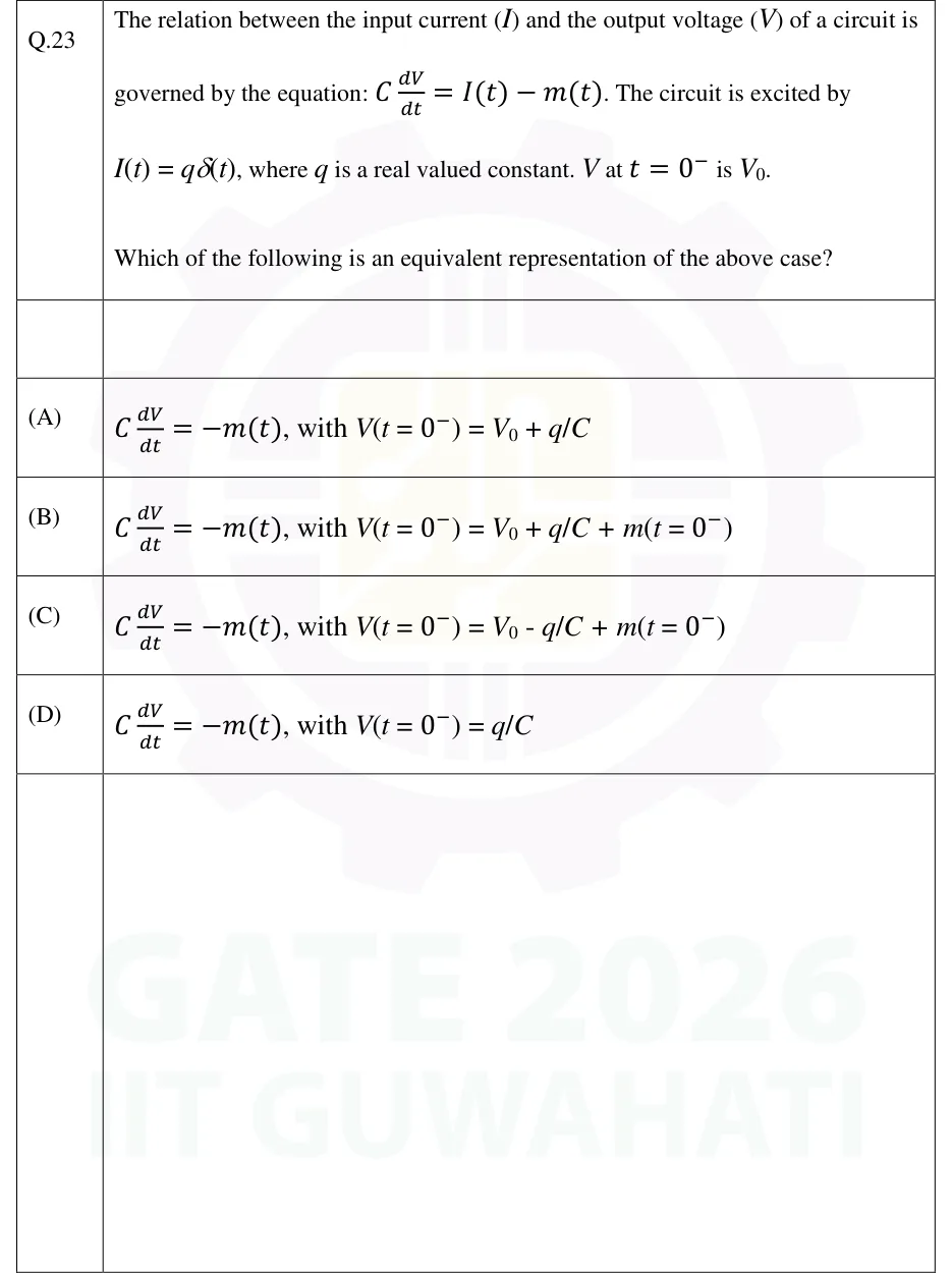
GATE 2026 EC Q.23

GATE 2026 · ECQ.23 · 1 mark · MCQ

The relation between the input current () and the output voltage () of a circuit is governed by the equation: . The circuit is excited by , where is a real valued constant. at is .

Which of the following is an equivalent representation of the above case?

  1. (A)

    , with

  2. (B)

    , with

  3. (C)

    , with

  4. (D)

    , with

Answer and solution
See the question in the paper
GATE 2026 EC Q.23: answer and solution

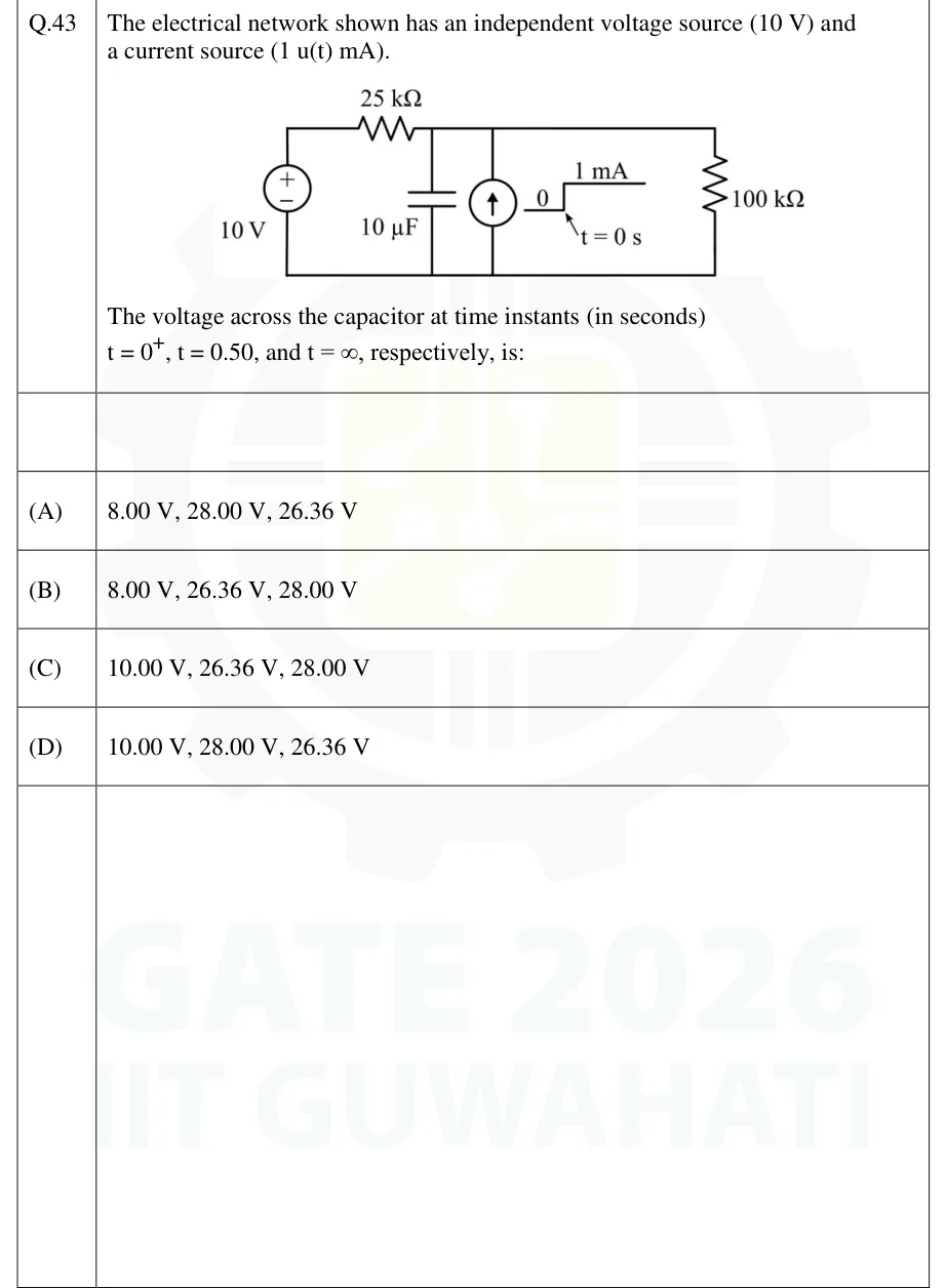
GATE 2026 EE Q.43

GATE 2026 · EEQ.43 · 2 marks · MCQ

The electrical network shown has an independent voltage source (10 V) and a current source (1 u(t) mA).

[Figure]

The voltage across the capacitor at time instants (in seconds) , , and , respectively, is:

GATE 2026 EE question 43: Single-node-pair circuit with a common bottom (reference) wire.Tap to open full size
Figure from the GATE 2026 EE paper. It is part of the question.
Figure description

Single-node-pair circuit with a common bottom (reference) wire. Left branch: independent 10 V DC source, + terminal on top, - terminal on the bottom wire. From the + terminal, a 25 kΩ resistor runs along the top wire to the top node. Between the top node and the bottom wire, three elements are connected in parallel, left to right: (1) a 10 µF capacitor; (2) an independent current source with its arrow pointing up (it drives current from the bottom wire into the top node). Its waveform is drawn beside it as a step: 0 before t = 0 s, jumping to 1 mA at t = 0 s (i.e. 1 u(t) mA); (3) a 100 kΩ resistor on the far right.

  1. (A)

    8.00 V, 28.00 V, 26.36 V

  2. (B)

    8.00 V, 26.36 V, 28.00 V

  3. (C)

    10.00 V, 26.36 V, 28.00 V

  4. (D)

    10.00 V, 28.00 V, 26.36 V

Answer and solution
GATE 2026 EE Q.43: answer and solution

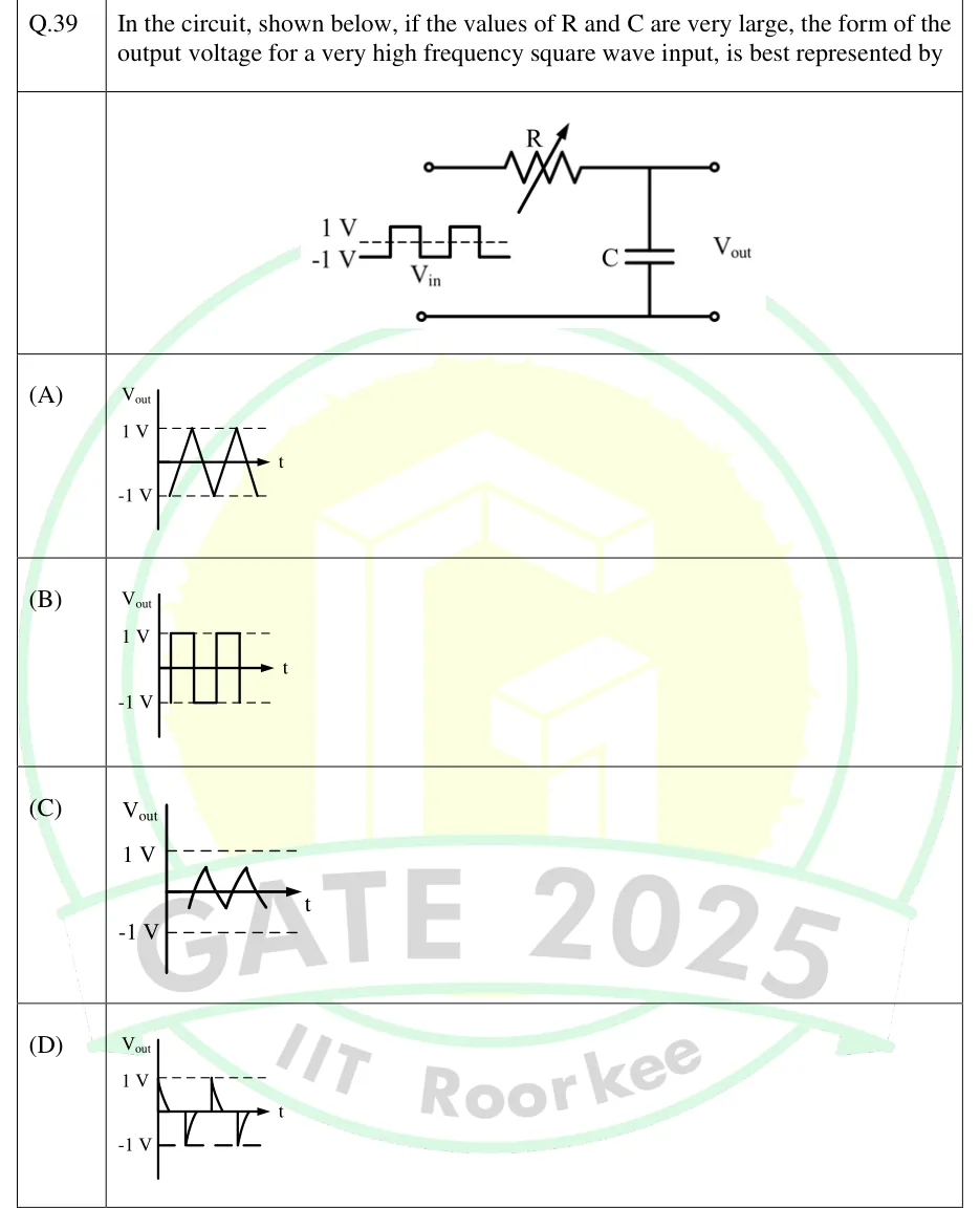
GATE 2025 EE Q.39

GATE 2025 · EEQ.39 · 2 marks · MCQ

In the circuit, shown below, if the values of R and C are very large, the form of the output voltage for a very high frequency square wave input, is best represented by

GATE 2025 EE question 39: Series RC low-pass network.Tap to open full size
Figure from the GATE 2025 EE paper. It is part of the question.
Figure description

Series RC low-pass network. From the top input terminal a variable resistor R (resistor symbol with a diagonal arrow through it) runs in series to a node. From that node a capacitor C goes down to the bottom (common) line, which runs straight from the bottom input terminal to the bottom output terminal. The output V_out is taken across the capacitor, between the top-right and bottom-right terminals. Next to the input terminals, the input V_in is sketched as a symmetric square wave that switches between +1 V and -1 V (labels '1 V' and '-1 V' at its high and low levels). It starts at -1 V on the left, and a single dashed line runs through the middle of the wave at the 0 V level.

  1. (A)

    Figure: vs t is a triangular wave swinging the full range between and . Its peaks and troughs touch the dashed 1 V and -1 V lines.

  2. (B)

    Figure: vs t is a square wave alternating between and (the same as the input).

  3. (C)

    Figure: vs t is a small-amplitude triangular wave centred on the time axis (symmetric about 0 V). Its peaks sit only a fraction of a volt above and below the axis, far inside the dashed 1 V and -1 V lines.

  4. (D)

    Figure: vs t is a train of exponential spikes. It starts at at t = 0 and decays to 0, stays at 0, jumps to at the next edge and decays back to 0, and so on alternately (a differentiated square wave).

Answer and solution
GATE 2025 EE Q.39: answer and solution

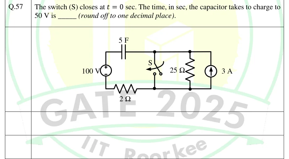
GATE 2025 EE Q.57

GATE 2025 · EEQ.57 · 2 marks · NAT

Q.57 The switch (S) closes at sec. The time, in sec, the capacitor takes to charge to 50 V is _____ (round off to one decimal place).

GATE 2025 EE question 57: A single-loop circuit with a parallel group on its right.Tap to open full size
Figure from the GATE 2025 EE paper. It is part of the question.
Figure description

A single-loop circuit with a parallel group on its right. Left vertical branch: a 100 V DC source with + at the top and - at the bottom. From the source's + terminal a top wire runs right through a 5 F capacitor to a top node A. From the source's - terminal a bottom wire runs right through a 2 Ω resistor to a bottom node B. Three vertical branches connect node A (top rail) to node B (bottom rail), from left to right: (1) switch S, drawn open, with an arrow showing it closes at t = 0; (2) a 25 Ω resistor; (3) a 3 A DC current source with its arrow pointing up, so it drives 3 A from B up into A. When S closes it shorts node A to node B, which also shorts out the 25 Ω resistor and the 3 A source.

Answer and solution
GATE 2025 EE Q.57: answer and solution

GATE 2025 IN Q.63

GATE 2025 · INQ.63 · 2 marks · NAT

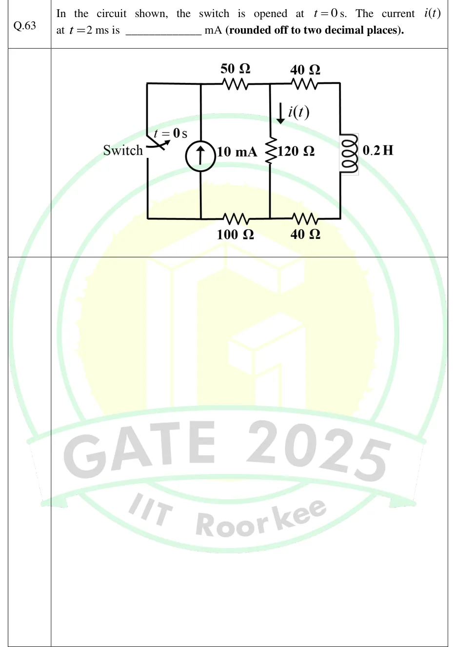
In the circuit shown, the switch is opened at s. The current at ms is ________ mA (rounded off to two decimal places).

GATE 2025 IN question 63: A ladder-type circuit.Tap to open full size
Figure from the GATE 2025 IN paper. It is part of the question.
Figure description

A ladder-type circuit. The nodes are not labelled in the figure; the letters here are for reference only: A top-left, B top-middle, D top-right, E bottom-right, C bottom-middle, F bottom-left. Leftmost vertical branch: a switch between A (top) and F (bottom), labelled 'Switch' and 't = 0 s'. It is closed for t < 0 and opens at t = 0. Next vertical branch, also between A and F: an independent 10 mA current source with its arrow pointing up, so it drives current from F into A. Top rail: a 50 Ω resistor from A to B, then a 40 Ω resistor from B to D. Middle vertical branch: a 120 Ω resistor from B down to C. It carries the current i(t), shown by a downward arrow (B to C). Rightmost vertical branch: a 0.2 H inductor from D down to E. Bottom rail: a 40 Ω resistor from E to C, then a 100 Ω resistor from C to F.

Answer and solution
GATE 2025 IN Q.63: answer and solution

GATE 2025 IN Q.64

GATE 2025 · INQ.64 · 2 marks · NAT

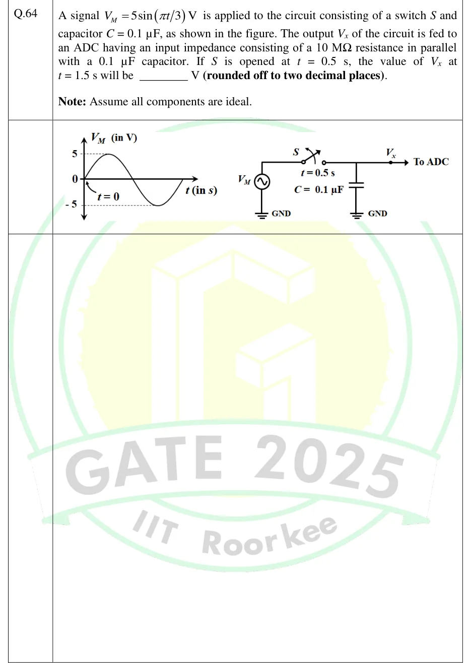
A signal V is applied to the circuit consisting of a switch and capacitor , as shown in the figure. The output of the circuit is fed to an ADC having an input impedance consisting of a resistance in parallel with a capacitor. If is opened at s, the value of at s will be ________ V (rounded off to two decimal places).

Note: Assume all components are ideal.

GATE 2025 IN question 64: Left: a plot of V_M (in V) against t (in s).Tap to open full size
Figure from the GATE 2025 IN paper. It is part of the question.
Figure description

Left: a plot of V_M (in V) against t (in s). The vertical axis is marked 5, 0 and -5, with dashed guide lines at +5 and -5. The waveform is one full sine cycle. It starts at 0 at t = 0 (an arrow labelled "t = 0" points to the origin), rises to +5, returns to 0, falls to -5 and returns to 0. The time axis has no numbered ticks. Right: the circuit. An AC voltage source V_M (a circle with a sine symbol) has its bottom terminal at GND. Its top terminal runs to switch S. The switch is drawn with its blade lifted and a curved arrow across it showing the opening action, with "t = 0.5 s" printed below it. From the switch the wire runs to the output node. Capacitor C = 0.1 (label printed to its left) goes from that node to GND. The wire continues right to a solid dot labelled V_x, and an arrow from the dot is labelled "To ADC". The ADC's input impedance (10 M Ω in parallel with 0.1) is given only in the text and is not drawn.

Answer and solution
GATE 2025 IN Q.64: answer and solution

GATE 2024 EC Q.32

GATE 2024 · ECQ.32 · 1 mark · NAT

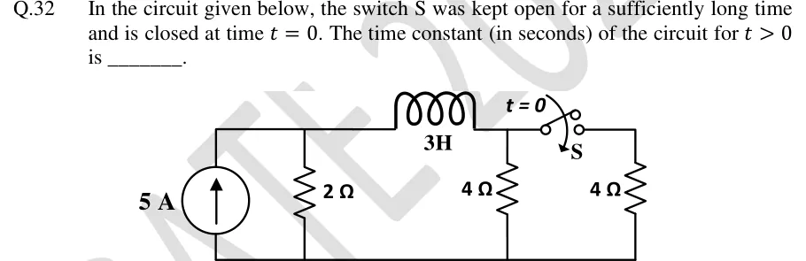
In the circuit given below, the switch S was kept open for a sufficiently long time and is closed at time . The time constant (in seconds) of the circuit for is ________.

GATE 2024 EC question 32: A ladder circuit on a common bottom (ground) rail.Tap to open full size
Figure from the GATE 2024 EC paper. It is part of the question.
Figure description

A ladder circuit on a common bottom (ground) rail. From left to right: an independent current source of 5 A, arrow pointing up (current delivered upward into the top-left node); a 2 Ω resistor connected from that top-left node to ground (in parallel with the source); a 3 H inductor in series along the top wire from the top-left node to a second top node; a 4 Ω resistor from the second top node to ground; then a switch S, labelled t = 0 (open before t = 0, closes at t = 0), in the top wire from the second top node to a third top node; a second 4 Ω resistor from the third top node to ground.

Answer and solution
GATE 2024 EC Q.32: answer and solution

GATE 2024 EE Q.14

GATE 2024 · EEQ.14 · 1 mark · MCQ

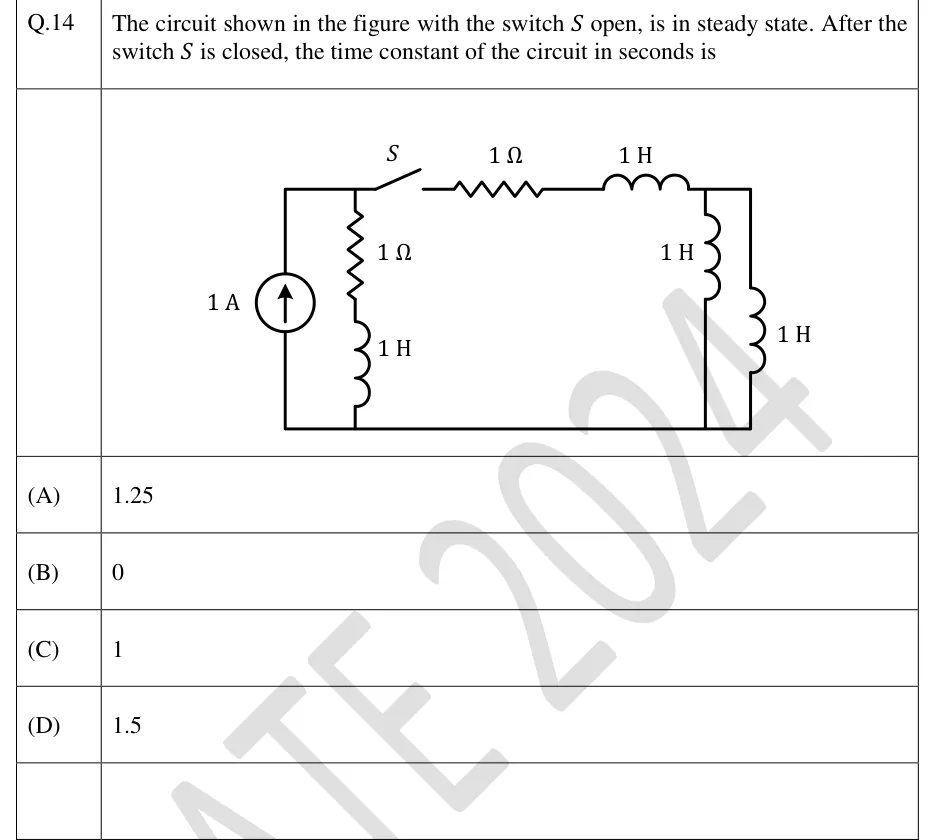
The circuit shown in the figure with the switch open, is in steady state. After the switch is closed, the time constant of the circuit in seconds is

GATE 2024 EE question 14: Two horizontal rails: a top wire and a bottom (reference) wire.Tap to open full size
Figure from the GATE 2024 EE paper. It is part of the question.
Figure description

Two horizontal rails: a top wire and a bottom (reference) wire. Left: an independent current source of 1 A, arrow pointing up, connected between the bottom rail and the top-left wire, so it drives 1 A up into the top-left node A. Just right of the source, a vertical branch from node A to the bottom rail made of a 1 Ω resistor in series with a 1 H inductor (resistor on top, inductor below), so this branch is in parallel with the current source. From node A the top wire runs right through switch S (drawn open; it closes at the switching instant), then a 1 Ω resistor, then a 1 H inductor, to the top-right node B. From node B two vertical 1 H inductors go down to the bottom rail, side by side, so they are in parallel with each other. No other elements. Before the switch closes, the right-hand part (1 Ω, 1 H and the two parallel 1 H inductors) is not connected to the source.

  1. (A)

    1.25

  2. (B)

    0

  3. (C)

    1

  4. (D)

    1.5

Answer and solution
GATE 2024 EE Q.14: answer and solution

GATE 2024 IN Q.33

GATE 2024 · INQ.33 · 1 mark · NAT

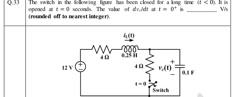
The switch in the following figure has been closed for a long time (). It is opened at seconds. The value of at is ________ V/s (rounded off to nearest integer).

GATE 2024 IN question 33: A single-loop-plus-branch circuit.Tap to open full size
Figure from the GATE 2024 IN paper. It is part of the question.
Figure description

A single-loop-plus-branch circuit. On the left, a 12 V DC source, + terminal at the top. From the top of the source a wire runs right through a 4 Ω resistor and then a 0.25 H inductor (current i_L(t) marked with an arrow pointing right, left to right through the inductor) to a top node. From this top node two branches go down to the bottom rail, which returns to the source's − terminal: (1) a vertical 4 Ω resistor in series with a switch, the switch being at the lower end of this branch, labelled 't = 0' and 'Switch' (closed for t < 0, opened at t = 0); (2) at the far right, a 0.1 F capacitor with voltage v_c(t) marked + at its top terminal (the top node) and − at its bottom terminal (the bottom rail).

Answer and solution
GATE 2024 IN Q.33: answer and solution

GATE 2023 EC Q.35

GATE 2023 · ECQ.35 · 1 mark · NAT

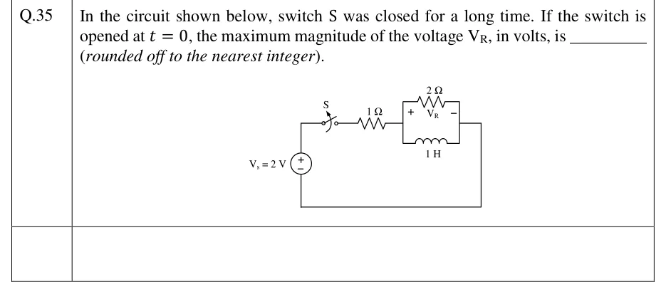
In the circuit shown below, switch S was closed for a long time. If the switch is opened at , the maximum magnitude of the voltage , in volts, is ________ (rounded off to the nearest integer).

GATE 2023 EC question 35: A single loop.Tap to open full size
Figure from the GATE 2023 EC paper. It is part of the question.
Figure description

A single loop. An ideal DC source V_s = 2 V is on the left branch, with its + terminal at the top. From the top of the source, the wire goes right through switch S, which is closed for a long time and opens at t = 0. Next comes a 1 Ω series resistor, then a parallel combination: a 2 Ω resistor on the upper branch and a 1 H inductor on the lower branch, both connected between a left node and a right node. The voltage V_R is marked across the 2 Ω resistor, + at the left node and − at the right node. From the right node the wire runs down and back along the bottom to the − terminal of the source.

Answer and solution
GATE 2023 EC Q.35: answer and solution

GATE 2023 EC Q.44

GATE 2023 · ECQ.44 · 2 marks · MCQ

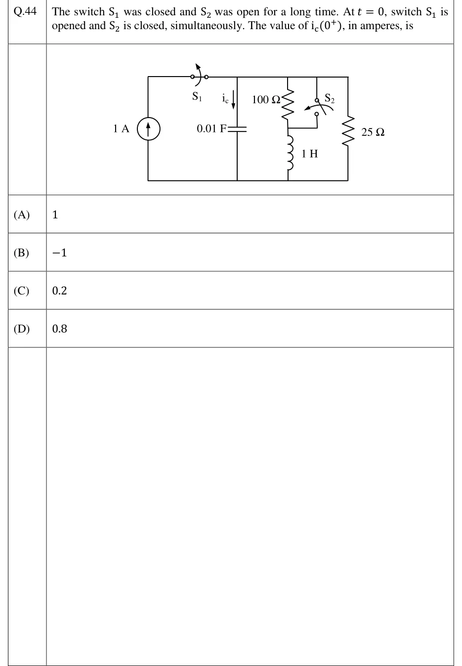
The switch was closed and was open for a long time. At , switch is opened and is closed, simultaneously. The value of , in amperes, is

GATE 2023 EC question 44: Parallel circuit with a common bottom rail and a top rail.Tap to open full size
Figure from the GATE 2023 EC paper. It is part of the question.
Figure description

Parallel circuit with a common bottom rail and a top rail. From left to right: (1) A 1 A independent current source (arrow pointing up) in the leftmost branch. Its top terminal connects to the top rail through switch S_1, which sits on the top wire just right of the source branch, so S_1 is in series with the source. S_1 is drawn with an arrow showing it opening. (2) A 0.01 F capacitor from the top rail to the bottom rail. The current i_c is marked flowing downward into the capacitor branch. (3) A branch with a 100 Ω resistor from the top rail down to a middle node M, then a 1 H inductor from M to the bottom rail. (4) Switch S_2: its upper terminal is wired to the top rail and its lower terminal is wired left to node M, the junction between the 100 Ω resistor and the inductor. Closing S_2 therefore short-circuits the 100 Ω resistor. S_2 is drawn with an arrow showing it closing. (5) A 25 Ω resistor from the top rail to the bottom rail in the rightmost branch. Before t = 0: S_1 closed, S_2 open. At t = 0: S_1 opens and S_2 closes at the same instant.

  1. (A)

    1

  2. (B)

  3. (C)

    0.2

  4. (D)

    0.8

Answer and solution
GATE 2023 EC Q.44: answer and solution

GATE 2023 EE Q.29

GATE 2023 · EEQ.29 · 1 mark · NAT

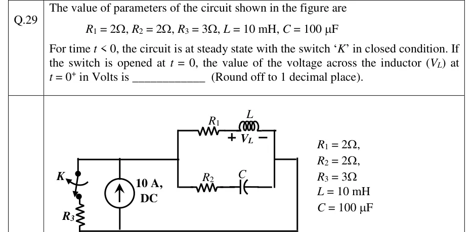
The value of parameters of the circuit shown in the figure are
, , , ,
For time , the circuit is at steady state with the switch 'K' in closed condition. If the switch is opened at , the value of the voltage across the inductor () at in Volts is ________ (Round off to 1 decimal place).

GATE 2023 EE question 29: A 10 A DC current source (arrow pointing up) is connected between a bottom wire (node B) and a top wire (node A).Tap to open full size
Figure from the GATE 2023 EE paper. It is part of the question.
Figure description

A 10 A DC current source (arrow pointing up) is connected between a bottom wire (node B) and a top wire (node A). On the left, between A and B, is a series branch of switch K (closed for t < 0, opens at t = 0) and resistor R3 = 3 Ω, with K at the top next to node A and R3 below it. On the right, node A continues to a vertical wire that feeds two parallel branches running left to right: the upper branch is R1 = 2 Ω in series with inductor L = 10 mH, with V_L marked across the inductor, + on the left (R1 side) and − on the right; the lower branch is R2 = 2 Ω in series with capacitor C = 100 μF. The right ends of the two branches join at a vertical wire, and a wire runs from there down and back along the bottom to node B. So three branches are in parallel across the current source: (K + R3), (R1 + L) and (R2 + C). The parameter values are repeated beside the figure.

Answer and solution
GATE 2023 EE Q.29: answer and solution

GATE 2023 EE Q.54

GATE 2023 · EEQ.54 · 2 marks · NAT

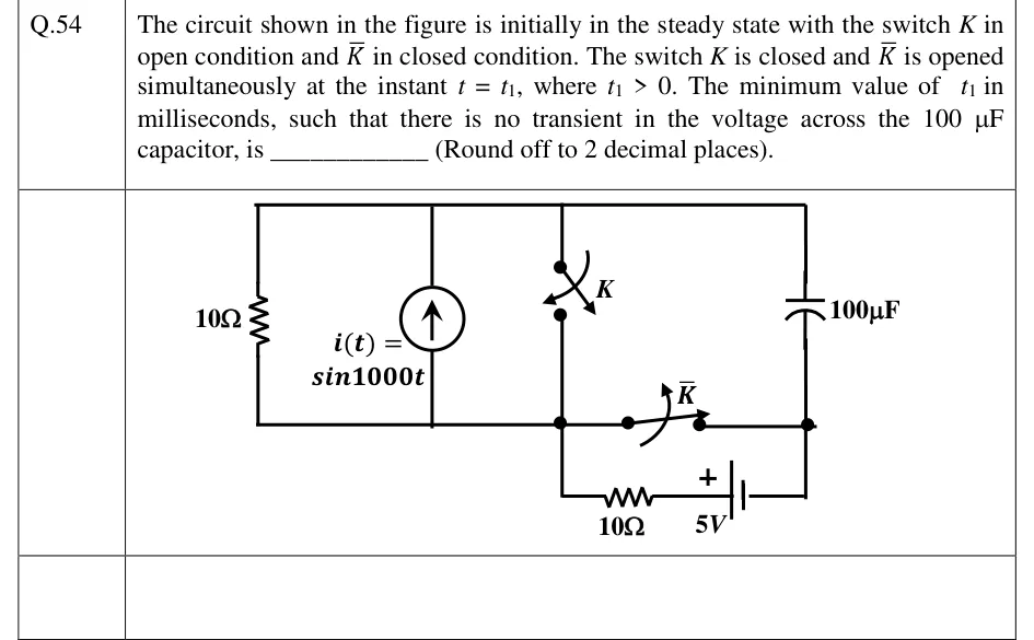
The circuit shown in the figure is initially in the steady state with the switch in open condition and in closed condition. The switch is closed and is opened simultaneously at the instant , where . The minimum value of in milliseconds, such that there is no transient in the voltage across the capacitor, is ________ (Round off to 2 decimal places).

GATE 2023 EE question 54: Three nodes: a top rail T, a bottom-left node M (drawn as a dot below switch K), and a bottom-right node R (a dot below…Tap to open full size
Figure from the GATE 2023 EE paper. It is part of the question.
Figure description

Three nodes: a top rail T, a bottom-left node M (drawn as a dot below switch K), and a bottom-right node R (a dot below the capacitor). Between T and M, from left to right, are three parallel branches: a 10 Ω resistor; an independent current source i(t) = sin 1000t with its arrow pointing up, so it drives current from M into T; and switch K, drawn open, connecting T to M. The 100 capacitor connects T to R on the right. Switch K, drawn closed, connects M to R directly along the bottom wire. Below that wire a second branch also runs from M to R: from M down, then a 10 Ω resistor, then a 5 V battery. The battery's positive terminal (long plate, marked +) faces the resistor and hence M, and its negative terminal faces R. Before t_1: K open, K closed. At t = t_1: K closes and K opens.

Answer and solution
GATE 2023 EE Q.54: answer and solution

GATE 2023 IN Q.47

GATE 2023 · INQ.47 · 2 marks · NAT

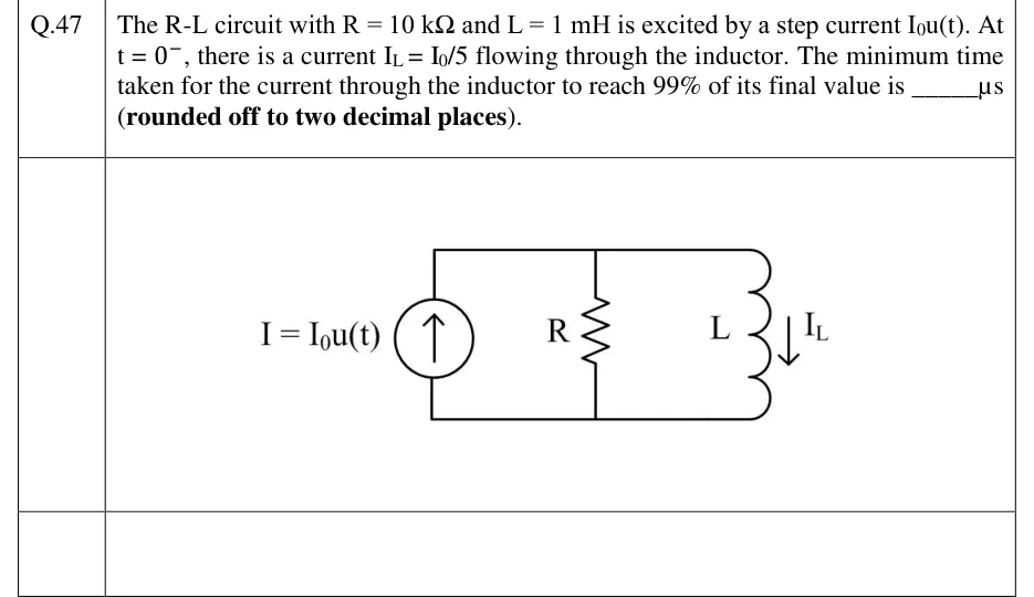
The R-L circuit with and is excited by a step current . At , there is a current flowing through the inductor. The minimum time taken for the current through the inductor to reach 99% of its final value is ______ (rounded off to two decimal places).

GATE 2023 IN question 47: Three elements connected in parallel between a top rail and a bottom rail.Tap to open full size
Figure from the GATE 2023 IN paper. It is part of the question.
Figure description

Three elements connected in parallel between a top rail and a bottom rail. Left branch: an independent current source labelled I = I_0u(t) with its arrow pointing upward (current delivered into the top rail). Middle branch: resistor R. Right branch: inductor L, with the inductor current I_L marked by an arrow pointing downward (from the top rail through L to the bottom rail). No switch; the excitation is the step I_0u(t).

Answer and solution
GATE 2023 IN Q.47: answer and solution

GATE 2022 EE Q.31

GATE 2022 · EEQ.31 · 1 mark · NAT

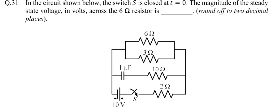
In the circuit shown below, the switch is closed at . The magnitude of the steady state voltage, in volts, across the resistor is ________. (round off to two decimal places).

GATE 2022 EE question 31: Three branches are connected in parallel between a left vertical rail and a right vertical rail.Tap to open full size
Figure from the GATE 2022 EE paper. It is part of the question.
Figure description

Three branches are connected in parallel between a left vertical rail and a right vertical rail. Top branch: a 6 Ω resistor and a 3 Ω resistor in parallel with each other, the 6 Ω drawn above the 3 Ω. Their two ends join short vertical links, and horizontal wires tie those links to the outer left and right rails. Middle branch: a 1 capacitor in series with a 10 Ω resistor, capacitor on the left side and 10 Ω on the right, from the left rail to the right rail. Bottom branch: a 10 V battery at the bottom-left (negative terminal on the left, toward the left rail; positive terminal on the right), then switch S (open in the drawing, closed at t = 0), then a 2 Ω resistor running to the right rail.

Answer and solution
GATE 2022 EE Q.31: answer and solution

GATE 2022 IN Q.62

GATE 2022 · INQ.62 · 2 marks · NAT

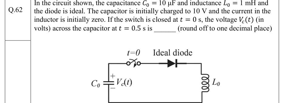
In the circuit shown, the capacitance and inductance and the diode is ideal. The capacitor is initially charged to 10 V and the current in the inductor is initially zero. If the switch is closed at s, the voltage (in volts) across the capacitor at s is ______ (round off to one decimal place)

GATE 2022 IN question 62: A single series loop.Tap to open full size
Figure from the GATE 2022 IN paper. It is part of the question.
Figure description

A single series loop. The left branch is capacitor C0, drawn vertically, with its + terminal at the top and - terminal at the bottom, labelled V_c(t). From the top of C0 a wire runs right through a switch (labelled t=0, open before t = 0 and closing at t = 0), then through an ideal diode whose anode is on the left and cathode on the right (arrow pointing right, away from the capacitor's + terminal). The wire continues to the top right corner and down through inductor L0 on the right branch, then along the bottom wire back to the - terminal of C0. There are no other elements.

Answer and solution
GATE 2022 IN Q.62: answer and solution

GATE 2022 IN Q.64

GATE 2022 · INQ.64 · 2 marks · NAT

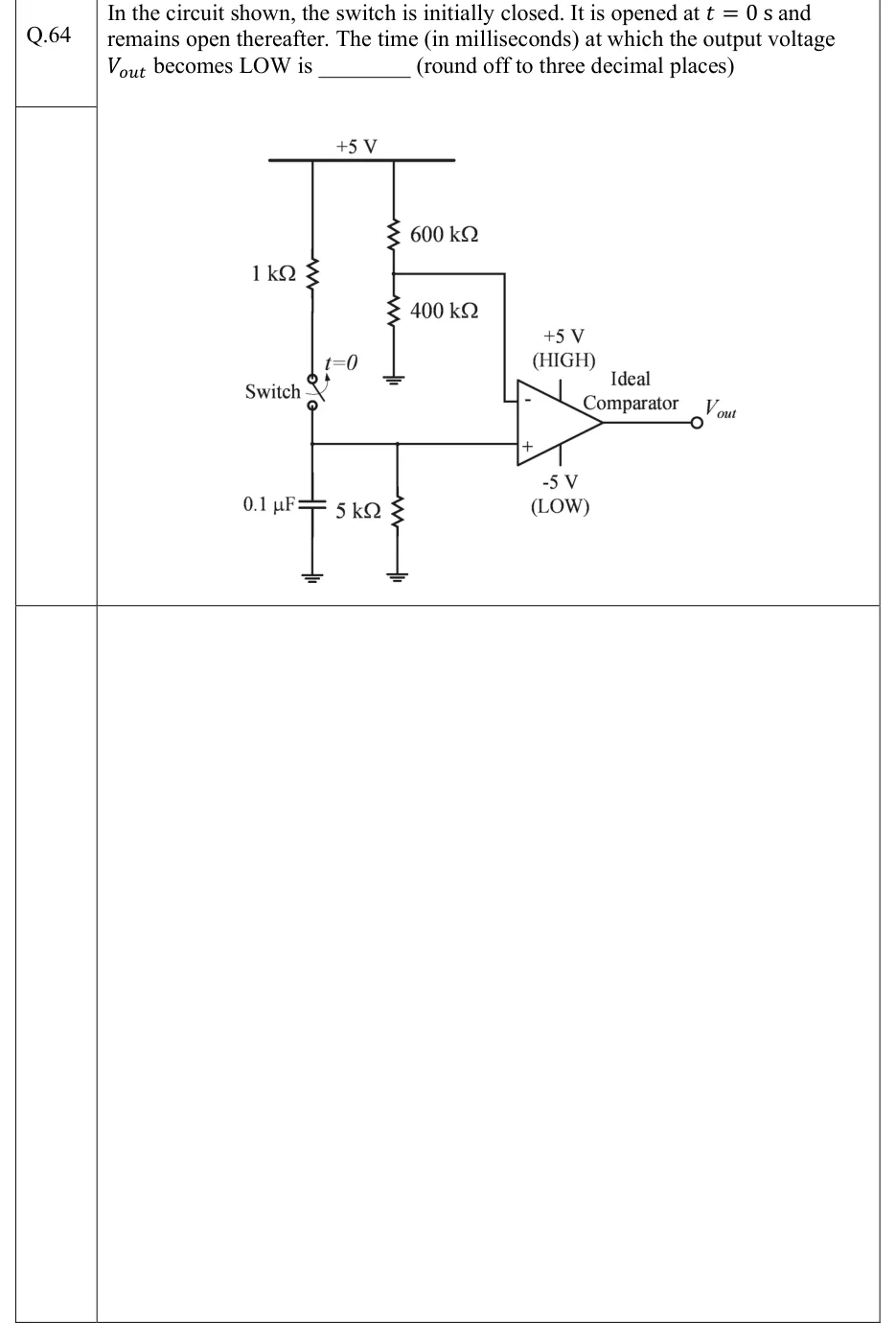
In the circuit shown, the switch is initially closed. It is opened at s and remains open thereafter. The time (in milliseconds) at which the output voltage becomes LOW is ________ (round off to three decimal places)

GATE 2022 IN question 64: A +5 V supply rail runs along the top.Tap to open full size
Figure from the GATE 2022 IN paper. It is part of the question.
Figure description

A +5 V supply rail runs along the top. Left branch: a 1 kΩ resistor hangs from the +5 V rail down to a switch labelled 'Switch'. The switch is shown closed and is marked t=0 with an arrow showing that it opens at t = 0. The lower terminal of the switch goes to node X. At node X, a 0.1 µF capacitor goes to ground, a 5 kΩ resistor goes to ground, and a wire goes to the non-inverting (+) input of an ideal comparator. Right branch: a potential divider hangs from the +5 V rail, with 600 kΩ on top and 400 kΩ below it to ground. The junction of the 600 kΩ and 400 kΩ resistors goes to the inverting (−) input of the comparator. The comparator is labelled 'Ideal Comparator'. Its output saturates at +5 V (HIGH) and −5 V (LOW), and the output terminal is labelled V_out.

Answer and solution
GATE 2022 IN Q.64: answer and solution

GATE 2020 EE Q.45

GATE 2020 · EEQ.45 · 2 marks · NAT

A resistor and a capacitor are connected in series to a 10 V dc supply through a switch. The switch is closed at , and the capacitor voltage is found to cross 0 V at , where is the circuit time constant. The absolute value of percentage change required in the initial capacitor voltage if the zero crossing has to happen at is ________ (rounded off to 2 decimal places).

Answer and solution
See the question in the paper
GATE 2020 EE Q.45: answer and solution

GATE 2018 EC Q.36

GATE 2018 · ECQ.36 · 2 marks · NAT

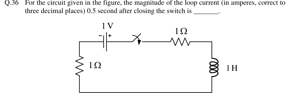
For the circuit given in the figure, the magnitude of the loop current (in amperes, correct to three decimal places) 0.5 second after closing the switch is ________.

GATE 2018 EC question 36: A single series loop drawn as a rectangle.Tap to open full size
Figure from the GATE 2018 EC paper. It is part of the question.
Figure description

A single series loop drawn as a rectangle. Top side, left to right: a 1 V battery (negative terminal marked '-' on the left, positive terminal '+' on the right), then a switch drawn in the open position (no closing-time label is printed), then a 1 Ω resistor. Right side: a 1 H inductor running from the top-right corner to the bottom-right corner. Bottom side: a plain wire. Left side: a 1 Ω resistor running from the bottom-left corner up to the top-left corner, where it meets the battery's negative terminal. Everything is in one series loop: battery, switch, 1 Ω, 1 H, then 1 Ω back to the battery.

Answer and solution
GATE 2018 EC Q.36: answer and solution

GATE 2018 EE Q.31

GATE 2018 · EEQ.31 · 2 marks · MCQ

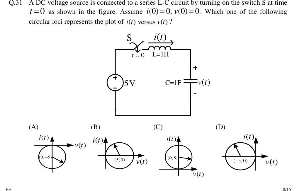
A DC voltage source is connected to a series L-C circuit by turning on the switch S at time as shown in the figure. Assume . Which one of the following circular loci represents the plot of versus ?

GATE 2018 EE question 31: Single series loop.Tap to open full size
Figure from the GATE 2018 EE paper. It is part of the question.
Figure description

Single series loop. Left branch: a 5 V DC voltage source, + terminal at the top, - at the bottom. From the top of the source the wire goes right through switch S (closes at t = 0), then an inductor L = 1 H; the current i(t) is marked with an arrow pointing rightward (clockwise around the loop) above the inductor. Right branch: capacitor C = 1 F, with its voltage v(t) marked + at the top and - at the bottom. Bottom wire returns from the capacitor to the - terminal of the source. Options are four plots, each with v(t) on the horizontal axis and i(t) on the vertical axis, showing a circle with a radius arrow drawn from its labelled centre: (A) circle centred at (0, -5), lying below the v-axis and touching it at the origin; (B) circle centred at (5, 0), lying to the right of the i-axis and touching it at the origin; (C) circle centred at (0, 5), lying above the v-axis and touching it at the origin; (D) circle centred at (-5, 0), lying to the left of the i-axis and touching it at the origin.

  1. (A)

    Figure — circle of radius 5 centred at in the – plane (below the axis, tangent to it at the origin)

  2. (B)

    Figure — circle of radius 5 centred at in the – plane (right of the axis, tangent to it at the origin)

  3. (C)

    Figure — circle of radius 5 centred at in the – plane (above the axis, tangent to it at the origin)

  4. (D)

    Figure — circle of radius 5 centred at in the – plane (left of the axis, tangent to it at the origin)

Answer and solution
GATE 2018 EE Q.31: answer and solution

PRACTICE

5 questions to test yourself

PRACTICE 11 mark · NAT

A 10 V DC source, a switch S, a 2 kΩ resistor and a 5 µF capacitor are connected in series. Just before S closes at , the capacitor voltage is 2 V, with the same polarity the source would charge it to. The capacitor voltage (in V, same polarity) at ms is ______ (round off to two decimal places).

Answer and solution

Answer: (accepted range )

  1. V; V, since the capacitor is an open circuit in DC steady state.

  2. ms.

  3. V V.

PRACTICE 21 mark · MCQ

A source-free parallel RLC circuit has , H and F. Its natural response is

  1. (A)

    underdamped, with and rad/s

  2. (B)

    critically damped, with a repeated root at

  3. (C)

    overdamped, with natural frequencies and

  4. (D)

    undamped, oscillating at 2 rad/s

Answer and solution

Answer: (C)

  1. rad/s.

  2. For a parallel RLC, .

  3. , so the response is overdamped: .

  4. Option A is what the series formula would give, and that formula does not apply to a parallel circuit.

PRACTICE 31 mark · MCQ

A 4 µF capacitor charged to 50 V and a 1 µF capacitor charged to 10 V are connected in parallel through a 100 Ω resistor at , with their positive terminals joined. After the transient has died out, the common capacitor voltage and the total energy dissipated in the resistor are

  1. (A)

    42 V and 0.64 mJ

  2. (B)

    30 V and 0.64 mJ

  3. (C)

    42 V and 1.28 mJ

  4. (D)

    30 V and 1.28 mJ

Answer and solution

Answer: (A)

  1. Charge is conserved: V.

  2. Energy lost mJ.

  3. Check: the initial energy is mJ and the final energy is mJ. The difference, 0.64 mJ, is all dissipated in the resistor, whatever its value.

PRACTICE 42 marks · MSQ

A 12 V DC source, a switch S and a 4 Ω resistor are connected in series between node a and the ground node g, with the source's + terminal toward a. Two more branches are connected between a and g: a 0.5 F capacitor, and a 2 H inductor in series with a 2 Ω resistor. S has been closed for a long time and opens at , removing the source branch. Take as the voltage of node a with respect to g, and as the inductor current flowing from a toward g. Which of the following is/are correct?

  1. (A)

    V and A

  2. (B)

    at is V/s

  3. (C)

    at is A/s

  4. (D)

    For the natural response is underdamped, with damped natural frequency rad/s

Answer and solution

Answer: (A), (B), (D)

  1. For , in DC steady state, the capacitor is open and the inductor is a short. The source drives A through the 4 Ω resistor, the inductor and the 2 Ω resistor, so A. The capacitor is across the inductor branch, so V.

  2. By continuity, V and A. (A) is correct.

  3. For the capacitor and the inductor branch form a single loop. KCL at node a, with flowing from a to g through C: , so A and V/s. (B) is correct.

  4. , so . (C) is wrong.

  5. The loop is a series RLC with , H and F: and rad/s. It is underdamped with rad/s. (D) is correct.

PRACTICE 52 marks · NAT

The voltage V ( in seconds, argument in radians) is switched on at across a series circuit of and H, which carries no current before switching. The current (in A) at s ( ms) is ______ (round off to two decimal places).

Answer and solution

Answer: (accepted range )

  1. , so , rad and A.

  2. s ms.

  3. With switching angle : A.

  4. At s, , so . Also , , and .

  5. A.

OFFICIAL GATE 2027 SYLLABUS WORDING

Copied from the GATE 2027 syllabus; see all 2027 syllabi.

GATE EC

Time and frequency domain analysis of linear circuits: RL, RC and RLC circuits, solution of network equations using Laplace transform

GATE EE

Transient response of DC and AC networks

GATE IN

transient analysis of RC, RL, LC, RLC circuits … transient analysis of RLC circuits with AC excitation

Preparing in Kolkata? IAE Academy's course for GATE ECE, GATE EE or GATE IN.