IAE Academy

GATE EC · EE · IN

Two-port networks

A two-port network is any linear circuit reached through two pairs of terminals, described by four parameters that relate its two port voltages to its two port currents. The six standard sets (, , , , ABCD and inverse ABCD) are six ways of writing the same linear relation, wherever each set exists. Typical problems ask you to find a parameter set from a circuit (often one with a dependent source), convert between sets, test reciprocity and symmetry, combine networks in series, parallel or cascade, and find the input impedance or gain of a terminated two-port. Every one of these comes down to the definitions and sign conventions collected here.

11 previous-year questions · 11 solved · 5 practice questions

Ports, sign convention and the six descriptions

A two-port is a linear network that the outside world reaches only through two pairs of terminals: port 1 (usually the input, with and ) and port 2 (usually the output, with and ). Each pair must satisfy the port condition: the current entering one terminal of a port leaves by the other terminal of the same port. The network may contain , , , coupled coils, ideal transformers and dependent (controlled) sources. It must contain no independent sources and no nonzero initial conditions, because otherwise the parameter equations pick up extra constant terms.

Sign convention used throughout these notes. and are taken with at the upper terminal of each port, and and both flow into the network at the upper terminal. So when port 2 feeds a load , the current in the load is and . Port quantities are phasors at one frequency, or Laplace transforms with zero initial conditions. Every parameter is a ratio of two of these quantities, so rms and peak phasors give the same parameters, provided all four are of the same kind.

Of the four port variables , any two can be chosen as independent and the other two written in terms of them. That gives parameter sets. All six describe the same network (a particular set may fail to exist for a particular network; see below). Which one to use depends on how the network is tested or connected to other networks.

The six parameter sets

Parameter set

Written for

In terms of

Natural use

Impedance (open-circuit)

Series connection, T equivalent, mesh analysis

Admittance (short-circuit)

Parallel connection, equivalent, nodal analysis

Hybrid

Series-parallel connection, small-signal transistor models

Inverse hybrid

Parallel-series connection

Transmission (ABCD)

Cascade connection, ladders, transmission lines

Inverse transmission

Cascade described from port 2 towards port 1

Definitions and test conditions

Each parameter is read off by setting one independent variable to zero. Setting a current to zero means leaving that port open. Setting a voltage to zero means shorting that port. That is where the names open-circuit parameters () and short-circuit parameters () come from.

Z (OPEN-CIRCUIT IMPEDANCE) PARAMETERS

All four are in ohms, and each is measured with the other port open. and are driving-point (input and output) impedances. and are transfer impedances.

Y (SHORT-CIRCUIT ADMITTANCE) PARAMETERS

All four are in siemens, and each is measured with the other port shorted. whenever both exist. In general , because the two are measured under different terminations.

H (HYBRID) PARAMETERS

is the short-circuit input impedance (ohms), the open-circuit reverse voltage gain, the short-circuit forward current gain, and the open-circuit output admittance (siemens). Port 2 is shorted for and ; port 1 is open for and .

G (INVERSE HYBRID) PARAMETERS

whenever both exist. is the open-circuit input admittance (siemens), the short-circuit reverse current gain, the open-circuit forward voltage gain, and the short-circuit output impedance (ohms).

ABCD (TRANSMISSION) PARAMETERS

Written out, and . and are dimensionless, is in ohms and in siemens. and are measured with port 2 open, and with port 2 shorted. The minus sign is there because is the current that leaves port 2 and enters whatever is connected to it.

INVERSE TRANSMISSION PARAMETERS

and with port 1 open (); and with port 1 shorted (). Note that : the off-diagonal signs differ because of the terms.

Which port is opened or shorted

Test condition

Parameters measured under it

Port 2 open ()

, , , , ,

Port 1 open ()

, , , , ,

Port 2 shorted ()

, , , , ,

Port 1 shorted ()

, , , , ,

Finding the parameters of a given circuit

  1. Mark with the convention above: both currents enter the network at the upper terminals.

  2. Apply the test condition of the parameter asked for. Open a port by setting its current to zero (leave its terminals free); short a port by joining its terminals, so its voltage is zero.

  3. Drive the remaining port with a test source (a 1 A current source or a 1 V voltage source makes the ratio read off directly) and solve with KVL and KCL. Keep every dependent source in the circuit.

  4. Repeat with the roles of the two ports exchanged to get the other two parameters.

  5. Faster route, for a network whose two ports share a common lower terminal: write mesh equations in which is the only mesh current through port 1 and the only mesh current through port 2 (this gives directly), or nodal equations at the two upper port terminals with the common terminal as reference (this gives directly). Eliminate any internal mesh currents or node voltages first, then convert to the set asked for.

WHERE THE MINUS SIGNS LIVE

Only , (and , ) carry a minus sign in their definitions. With port 2 shorted, current flows out of the network through the short. So in a resistive network with a common lower terminal (a ladder, T or ), is negative and and come out positive. In a bridge or lattice, and can come out negative, and that is not an error. If a question draws leaving the network, change the sign of before you use these definitions.

Reciprocity, symmetry and conversion between sets

A two-port is reciprocal if an ideal voltage source at one port and an ideal ammeter at the other can be interchanged without changing the ammeter reading (equivalently, a current source and a voltmeter). Every network built only from , , , coupled coils and ideal transformers is reciprocal. Dependent sources usually destroy reciprocity, so a network that contains one has to be tested, not assumed. A two-port is symmetric if its ports look alike from outside: for every load, the input impedance at port 1 with that load on port 2 equals the input impedance at port 2 with the same load on port 1. A mirror-image circuit is symmetric, but a circuit can also be electrically symmetric without looking symmetric on paper.

CONDITION FOR RECIPROCITY

Any one of these implies all the others (for the sets that exist). A reciprocal two-port has only three independent parameters.

CONDITION FOR SYMMETRY

These express electrical symmetry of the two ports, and they hold whether or not the network is reciprocal. For a network that is also reciprocal, only two parameters are independent (for example and ). Ports that can be swapped with no change at all need both and .

DETERMINANTS AND QUICK IDENTITIES

Use for a quick reciprocity check from any set. The determinant of a product is the product of the determinants, so after multiplying the ABCD matrices of reciprocal sections (built from , , , coupled coils and ideal transformers), must still equal 1. That catches arithmetic slips.

Conversion table

Each row gives the set on the left in terms of the set named in the column. , , , . The remaining sets follow from , the formulas below, and the formula above.

Set

from

from

from (ABCD)

from

Z AND ABCD

exists only if ; exists only if .

Y AND ABCD

exists only if ; exists only if .

H FROM Z AND FROM Y

Note the pairs that are true reciprocals, each pair measured under the same termination: (port 2 shorted), (port 1 open), (port 2 open) and (port 1 shorted).

G FROM Z, FROM Y AND FROM ABCD

is the open-circuit forward voltage gain. exists only if (equivalently ).

WHEN A PARAMETER SET DOES NOT EXIST

A set exists only if its matrix is finite. A single series impedance between the upper terminals has no : it forces , so the two currents cannot be chosen independently. A single shunt element across the ports has no : it forces . An ideal transformer has neither nor . exists for all three. In the conversion table this shows up as a zero denominator ( or ). The other matrix does exist and is singular: a series impedance has , and a shunt impedance has .

Standard sections and T, pi equivalents

T NETWORK AND T EQUIVALENT

is the series arm at port 1, the series arm at port 2, and the shunt arm to the common terminal. Every reciprocal two-port that has a has this T equivalent, though an arm may come out negative (not realisable with positive elements). The T joins the two lower terminals, so it is equivalent only in its port voltages and currents.

PI NETWORK AND PI EQUIVALENT

is the shunt arm at port 1, the shunt arm at port 2, and the series arm between the upper terminals. Every reciprocal two-port that has a has this equivalent, with the same caveats as the T.

NON-RECIPROCAL T EQUIVALENT

When , build the T with in the shunt arm and add a current-controlled voltage source in the port-2 series arm, towards port 2. The dual: the built with , plus a voltage-controlled current source across port 2, its current directed from the upper terminal to the common terminal.

COUPLED COILS

Coil across port 1 and coil across port 2, mutual inductance , with both dots at the upper terminals, so both port currents enter dotted terminals. Moving one dot to its lower terminal changes to everywhere. In the -domain replace by . The T equivalent (which may need a negative inductance) holds only if the two lower terminals may be joined.

SYMMETRIC LATTICE

Series arms join upper terminal to upper terminal and lower terminal to lower terminal; cross arms join each upper terminal to the lower terminal of the other port. Its transfer impedance changes sign when .

ABCD matrices of standard sections

Section

Notes

Series impedance

No , since

Shunt admittance

No , since

Ideal transformer , dots at the upper terminals,

No or ; , ,

T: series , shunt , series

Symmetric when

: shunt , series , shunt

Symmetric when

BUILDING A LADDER

Get the ABCD matrix of any ladder by multiplying the matrices of its series and shunt elements in the order they appear from port 1 to port 2. Matrix multiplication does not commute: a series-then-shunt L section and a shunt-then-series L section have different ABCD matrices. Both still have .

Interconnection of two-ports

Two-ports and can be joined in five standard ways. Each connection is named by what happens at the input ports and at the output ports. For the four connections in which parameters add, the set that adds is the one whose independent variables are common to both networks. In a series connection the port currents are common, so the matrices add. In a parallel connection the port voltages are common, so the matrices add.

Interconnection rules

Connection

Input ports

Output ports

Rule

Series (series-series)

series

series

Parallel (parallel-parallel)

parallel

parallel

Series-parallel

series

parallel

Parallel-series

parallel

series

Cascade (tandem)

port 1 of

port 2 of (port 2 of drives port 1 of )

and

PARAMETER ADDITION

Valid only when each sub-network still satisfies the port condition after the connection (see the validity note below).

CASCADE CONNECTION

is the section nearer the source; keep the order. Always valid, because the current leaving is exactly the current entering . That is why the minus sign is built into the ABCD definition.

Validity of adding parameters (Brune's test), in brief

  1. Adding , , or is correct only if, after the connection, the current entering one terminal of each port of each sub-network still leaves by the other terminal of that port.

  2. Brune's test for a series connection: join the input ports in series and drive them, leave both output ports open and not yet joined, and check that the voltage across the gap between the two output terminals that the connection would join is zero. For a parallel connection: join the input ports in parallel and drive them, short each output port on its own, and check that the voltage between the two shorts is zero. Then repeat with the roles of the input and output sides exchanged.

  3. Cascade connection never needs the test.

  4. Two three-terminal networks (each with a common terminal shared by its two ports) connected in parallel with their common terminals joined always satisfy it. This is the usual case of two grounded networks in parallel, such as the twin-T.

  5. If the test fails, an ideal 1:1 transformer inserted at one port of one sub-network restores the port condition, and the addition rule applies again.

  6. When only the parameter matrices are given and there is no circuit to test, apply the rule directly.

WORKED EXAMPLE · CASCADE OF L SECTIONS

Section N is an L section: a resistor in series from the upper terminal of port 1 to the upper terminal of port 2, followed by a resistor across port 2. Two copies of N are cascaded. Find (a) the overall ABCD parameters, (b) the voltage gain with the output open, and (c) the input impedance when the output is terminated in .

Solution
  1. Multiply the series-element matrix by the shunt-element matrix, in the order they appear: . Check: .

  2. Cascade: . Check: .

  3. Output open (): , so . One section alone gives , but is wrong, because the second section loads the first.

  4. With : .

  5. Check by reducing the ladder from the load: , then , then , then . Each section turns a load into at its input.

Answer: , , , ; open-circuit gain ; .

RECOGNISING THE CONNECTION

Look at what the two networks share. A shared current at both ports means series, so add . A shared voltage at both ports means parallel, so add . The output of one feeding the input of the next means cascade, so multiply ABCD matrices in order. Never multiply the open-circuit gains of cascaded stages: each stage's gain depends on the load the next stage puts on it.

Terminated two-ports, dependent sources and image impedance

In use, port 2 feeds a load , so , and port 1 is driven by a source with internal impedance , so . Substituting these into the two parameter equations gives every input impedance, gain and Thevenin equivalent below. A driving-point impedance or admittance is a ratio of voltage and current at the same port (, , ; for a one-port, and with zero initial conditions). A transfer impedance relates the voltage at one port to the current at the other (, ).

INPUT IMPEDANCE OF A TERMINATED TWO-PORT

Port 2 terminated in (so ). As this becomes , the open-circuit input impedance; at it becomes , the short-circuit input impedance.

VOLTAGE AND CURRENT GAIN WITH A LOAD

Same termination, with port 1 driven directly by . The current delivered to the load is , so the load-current gain is . With the output open, .

THEVENIN EQUIVALENT AT PORT 2

Port 1 driven by in series with . For , set to zero, which leaves across port 1. With and fixed, the load receives maximum power when .

OPEN- AND SHORT-CIRCUIT IMPEDANCES

Each is measured at one port with the other port open (oc) or shorted (sc). For any two-port, . So only three of the four are independent.

IMAGE IMPEDANCES

The image impedances are the pair for which terminating port 2 in makes the input impedance at port 1 equal to , and terminating port 1 in makes the impedance at port 2 equal to . For a symmetric network both equal the characteristic impedance : a load is reproduced at the input. For a reciprocal network the image transfer constant satisfies , which becomes when the network is also symmetric.

Two-ports with dependent sources

  1. Keep every dependent source active. Only independent test sources are applied, at the ports.

  2. Write the controlling variable (, or a branch current) in terms of the port variables before forming the parameter equations.

  3. Apply the test condition and a test source, or write the two port equations directly by mesh or nodal analysis and read off the matrix.

  4. Expect (or ): test reciprocity, never assume it. A dependent source can also make an input impedance negative, and that is not an error.

  5. A T or equivalent of such a network needs an added controlled source (the non-reciprocal equivalents above).

WORKED EXAMPLE · DEPENDENT SOURCE, THEN A LOAD

A two-port has a common lower terminal. From the upper terminal of port 1, a resistor runs to an internal node X, and from X a resistor runs to the upper terminal of port 2. Between X and the common terminal is a branch made of a resistor in series with a current-controlled voltage source of value volts ( in amperes), with its terminal towards X. (a) Find and state whether the network is reciprocal and whether it is symmetric. (b) Port 2 is terminated in . Find the input impedance at port 1 and the voltage gain .

Solution
  1. With and entering at the upper terminals, the shunt branch carries from X down to the common terminal.

  2. Voltage of X: (the source adds because its terminal faces X).

  3. Port equations: and . So , , , (ohms).

  4. , so the network is not reciprocal (the dependent source is responsible). , so it is not symmetric.

  5. Load: . .

  6. , so .

  7. Cross-check with ABCD: , , , . Then (not 1, as expected), and .

Answer: , neither reciprocal nor symmetric; and .

RECIPROCAL PAIRS AND FALSE FRIENDS

in general, because is measured with port 2 open and with port 2 shorted. The correct relations are , and . Likewise is the short-circuit input impedance, not the image impedance .

PREVIOUS-YEAR QUESTIONS

11 questions from the EC, EE and IN papers

Try each question first, then open the answer. We placed each question under a topic ourselves; the exam paper does not label topics.

See these papers in full: GATE ECE 2026 · GATE ECE 2025 · GATE ECE 2024 · GATE ECE 2023 · GATE ECE 2020 · GATE ECE 2018 · GATE EE 2024 · GATE EE 2023 · GATE EE 2018 · GATE IN 2026

GATE 2026 EC Q.51

GATE 2026 · ECQ.51 · 2 marks · MCQ

Consider the two-port network as shown in the Figure.

Which of the following options provides the correct set of values of A, B, C and D parameters?
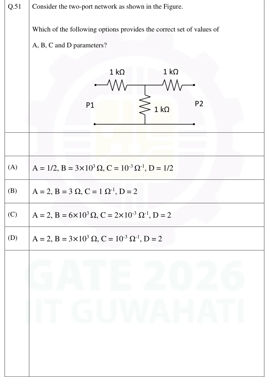
GATE 2026 EC question 51: A symmetrical T-network between port P1 (left pair of terminals) and port P2 (right pair of terminals).Tap to open full size
Figure from the GATE 2026 EC paper. It is part of the question.
Figure description

A symmetrical T-network between port P1 (left pair of terminals) and port P2 (right pair of terminals). The top line runs from the upper P1 terminal through a series 1 kΩ resistor to a central node, then through a second series 1 kΩ resistor to the upper P2 terminal. A 1 kΩ shunt resistor connects the central node down to the bottom line. The bottom line is a plain wire joining the lower P1 terminal to the lower P2 terminal (common return). No sources are present.

  1. (A)

    A = 1/2, B = 3×10^3 Ω, C = 10^-3 Ω^-1, D = 1/2

  2. (B)

    A = 2, B = 3 Ω, C = 1 Ω^-1, D = 2

  3. (C)

    A = 2, B = 6×10^3 Ω, C = 2×10^-3 Ω^-1, D = 2

  4. (D)

    A = 2, B = 3×10^3 Ω, C = 10^-3 Ω^-1, D = 2
Answer and solution
GATE 2026 EC Q.51: answer and solution

GATE 2026 IN Q.39

GATE 2026 · INQ.39 · 2 marks · MCQ

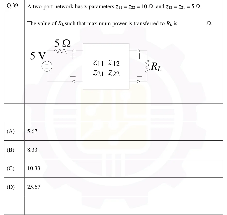
A two-port network has z-parameters , and .

The value of such that maximum power is transferred to is ________ .

GATE 2026 IN question 39: A two-port network is drawn as a box labelled with the matrix entries z11 z12 (top row) and z21 z22 (bottom row).Tap to open full size
Figure from the GATE 2026 IN paper. It is part of the question.
Figure description

A two-port network is drawn as a box labelled with the matrix entries z11 z12 (top row) and z21 z22 (bottom row). Port 1 on the left: a 5 V independent voltage source (+ at top, - at bottom) in series with a 5 Ω resistor. The resistor connects from the top of the source to the top terminal of port 1 (marked +). The bottom of the source goes to the bottom terminal of port 1 (marked -). Port 2 on the right: its top terminal (+) and bottom terminal (-) connect across a load resistor R_L.

  1. (A)

    5.67

  2. (B)

    8.33

  3. (C)

    10.33

  4. (D)

    25.67

Answer and solution
GATE 2026 IN Q.39: answer and solution

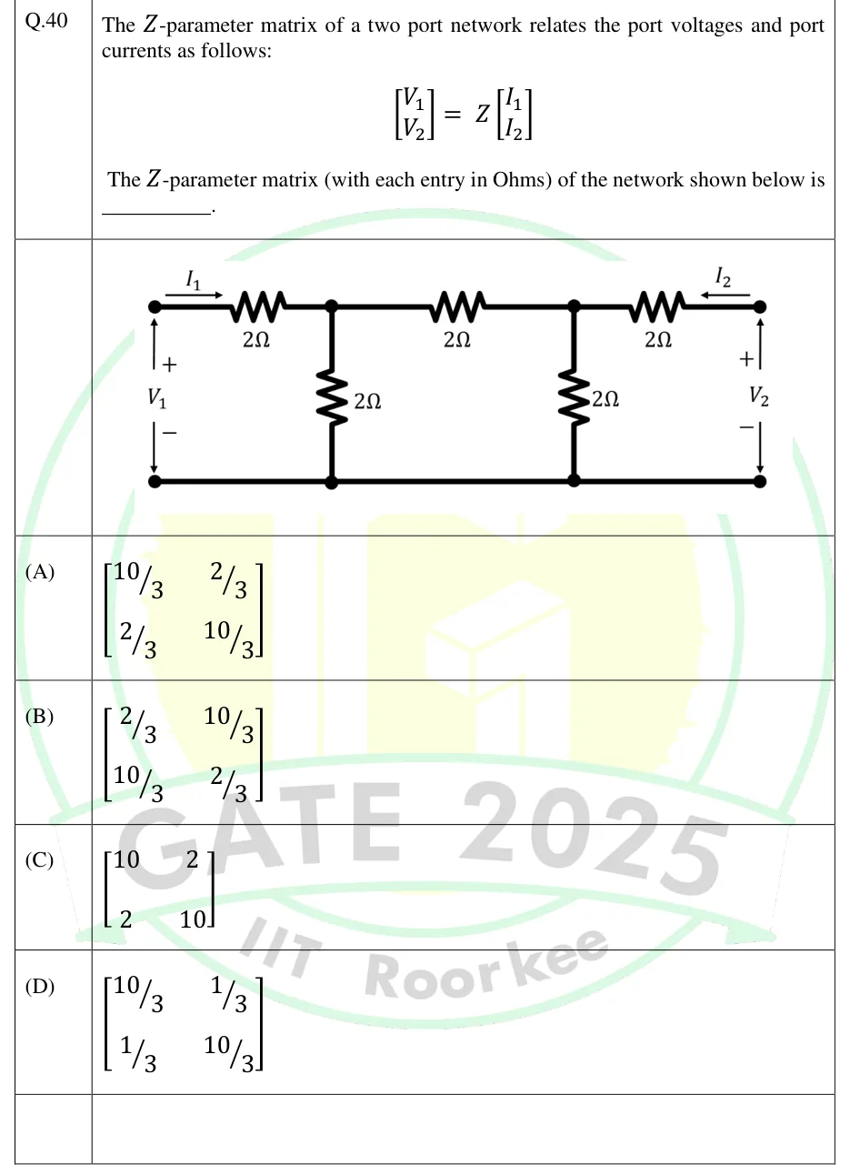
GATE 2025 EC Q.40

GATE 2025 · ECQ.40 · 2 marks · MCQ

The -parameter matrix of a two port network relates the port voltages and port currents as follows:

The -parameter matrix (with each entry in Ohms) of the network shown below is ________.

GATE 2025 EC question 40: A ladder two-port network with a common bottom (ground) rail.Tap to open full size
Figure from the GATE 2025 EC paper. It is part of the question.
Figure description

A ladder two-port network with a common bottom (ground) rail. Port 1 is on the left: V_1, + at the top terminal and − at the bottom terminal, and current I_1 flows into the top terminal (arrow pointing right). From the top-left terminal, a series 2 Ω resistor runs to node A. A shunt 2 Ω resistor connects node A to the bottom rail. A second series 2 Ω resistor runs from node A to node B. A shunt 2 Ω resistor connects node B to the bottom rail. A third series 2 Ω resistor runs from node B to the top-right terminal. Port 2 is on the right: V_2, + at the top terminal and − at the bottom terminal, and current I_2 flows into the top-right terminal (arrow pointing left, into the network). So there are five resistors, all 2 Ω: three in series along the top and two shunts to the bottom rail.

  1. (A)

  2. (B)

  3. (C)

  4. (D)

Answer and solution
GATE 2025 EC Q.40: answer and solution

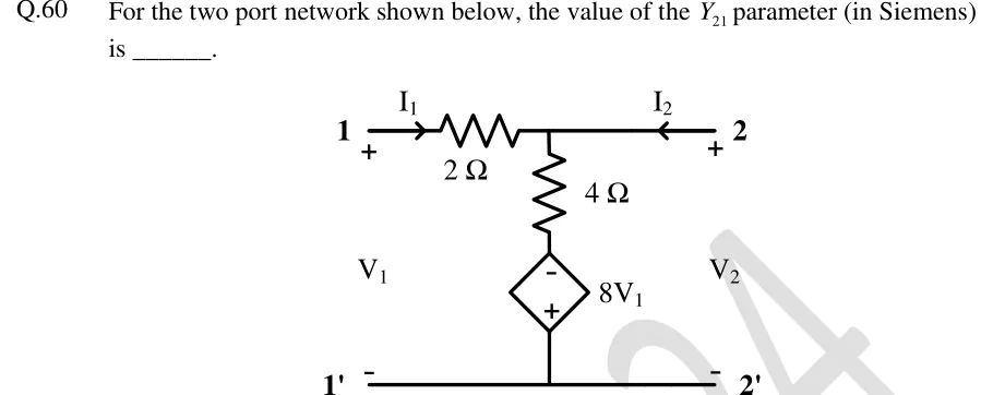
GATE 2024 EC Q.60

GATE 2024 · ECQ.60 · 2 marks · NAT

For the two port network shown below, the value of the parameter (in Siemens) is ______.

GATE 2024 EC question 60: A T-type two-port network.Tap to open full size
Figure from the GATE 2024 EC paper. It is part of the question.
Figure description

A T-type two-port network. Port 1 on the left: terminal 1 (top, marked +) and terminal 1' (bottom, marked -), port voltage V_1. Port 2 on the right: terminal 2 (top, marked +) and terminal 2' (bottom, marked -), port voltage V_2. Current I_1 enters terminal 1 (arrow pointing right, into the network); current I_2 enters terminal 2 (arrow pointing left, into the network). From terminal 1 a series 2 Ω resistor runs to a middle node N; terminal 2 is connected directly to node N by a wire (no series element on the port-2 side). From node N a 4 Ω resistor goes vertically down to a diamond-shaped dependent voltage source of value 8V_1 (voltage-controlled by the port-1 voltage V_1), whose '-' terminal is at the top (connected to the 4 Ω resistor) and '+' terminal at the bottom. The bottom of the source connects to the common bottom wire joining 1' and 2'.

Answer and solution
GATE 2024 EC Q.60: answer and solution

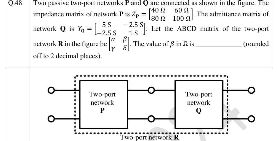
GATE 2024 EE Q.48

GATE 2024 · EEQ.48 · 2 marks · NAT

Two passive two-port networks and are connected as shown in the figure. The impedance matrix of network is . The admittance matrix of network is . Let the ABCD matrix of the two-port network in the figure be . The value of in is ________ (rounded off to 2 decimal places).

GATE 2024 EE question 48: Two boxes connected in cascade.Tap to open full size
Figure from the GATE 2024 EE paper. It is part of the question.
Figure description

Two boxes connected in cascade. Left box labelled 'Two-port network P', right box labelled 'Two-port network Q'. Two input terminals (open circles, top and bottom) on the far left connect to the input port of P. The two output-side wires of P run to a pair of intermediate open-circle terminals (top and bottom) and then into the input port of Q. The output port of Q connects to two open-circle terminals on the far right. A dashed rectangle encloses both P and Q (but not the outer terminals), labelled below as 'Two-port network R'. So R is the cascade (tandem) connection P followed by Q.

Answer and solution
GATE 2024 EE Q.48: answer and solution

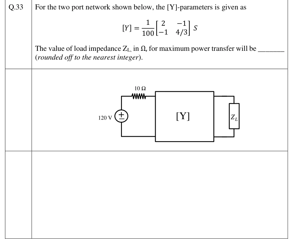
GATE 2023 EC Q.33

GATE 2023 · ECQ.33 · 1 mark · NAT

For the two port network shown below, the [Y]-parameters is given as

The value of load impedance , in , for maximum power transfer will be ________ (rounded off to the nearest integer).

GATE 2023 EC question 33: An ideal DC voltage source of 120 V (+ terminal at the top) is connected in series with a 10 Ω resistor to the input port…Tap to open full size
Figure from the GATE 2023 EC paper. It is part of the question.
Figure description

An ideal DC voltage source of 120 V (+ terminal at the top) is connected in series with a 10 Ω resistor to the input port (port 1, left side) of a two-port box labelled [Y]: the source's top terminal goes through the 10 Ω resistor to the upper input terminal, and the source's bottom terminal goes directly to the lower input terminal. The output port (port 2, right side) of the box is terminated by a load impedance Z_L connected across its two terminals.

Answer and solution
GATE 2023 EC Q.33: answer and solution

GATE 2023 EC Q.46

GATE 2023 · ECQ.46 · 2 marks · MCQ

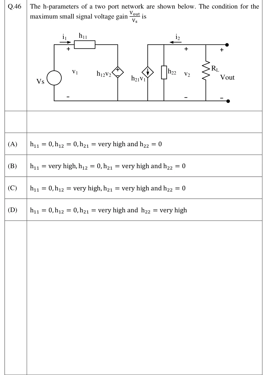
The h-parameters of a two port network are shown below. The condition for the maximum small signal voltage gain is

GATE 2023 EC question 46: Input side (left): an independent voltage source V_s (a circle with no polarity marks) in the left vertical branch.Tap to open full size
Figure from the GATE 2023 EC paper. It is part of the question.
Figure description

Input side (left): an independent voltage source V_s (a circle with no polarity marks) in the left vertical branch. From its top terminal a wire runs right through a resistor box labelled h_11. Current i_1 is marked by a right-pointing arrow above this wire, between the source and h_11. Voltage v_1 is marked + on the top wire just left of h_11 and − on the bottom rail, so it is across the source terminals. Right of h_11 the wire turns down through a dependent voltage source (diamond) labelled h_12v_2, + at top and − at bottom, to the bottom rail. Output side (right, on a separate top wire that starts above the first output element): three elements in parallel between this top wire and the bottom rail. From left to right they are a dependent current source (diamond) labelled h_21v_1 (printed with v_1, not i_1) with its arrow pointing DOWN, an admittance box labelled h_22, and a load resistor R_L. Between the h_22 box and R_L, current i_2 is marked by a LEFT-pointing arrow on the top wire (from the load into the network), and voltage v_2 is marked + at top and − at bottom. At the far right, two filled terminal dots (top and bottom) carry V_out, + at top and − at bottom, so V_out = v_2, the voltage across R_L. The bottom rail is one continuous wire from V_s to the bottom output terminal.

  1. (A)

  2. (B)

  3. (C)

  4. (D)

Answer and solution
GATE 2023 EC Q.46: answer and solution

GATE 2023 EE Q.52

GATE 2023 · EEQ.52 · 2 marks · NAT

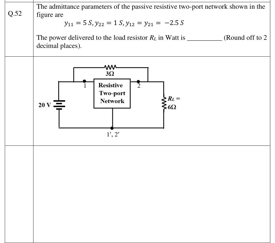
The admittance parameters of the passive resistive two-port network shown in the figure are

The power delivered to the load resistor in Watt is ________ (Round off to 2 decimal places).

GATE 2023 EE question 52: A box labelled 'Resistive Two-port Network' has input terminal 1 (top left), output terminal 2 (top right) and a common…Tap to open full size
Figure from the GATE 2023 EE paper. It is part of the question.
Figure description

A box labelled 'Resistive Two-port Network' has input terminal 1 (top left), output terminal 2 (top right) and a common bottom terminal labelled 1', 2'. A 20 V DC source (battery symbol) is connected across port 1, between terminal 1 and the common bottom node. A load resistor R_L = 6 Ω is connected across port 2, between terminal 2 and the common bottom node. A 3 Ω resistor is connected directly between terminal 1 and terminal 2, across the top of the box, so it is in parallel with the two-port (a bridging element from the input top node to the output top node).

Answer and solution
GATE 2023 EE Q.52: answer and solution

GATE 2020 EC Q.15

GATE 2020 · ECQ.15 · 1 mark · NAT

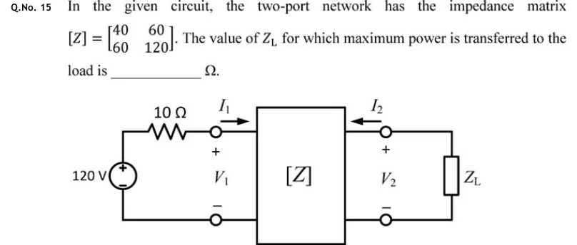
In the given circuit, the two-port network has the impedance matrix . The value of for which maximum power is transferred to the load is ________ .

GATE 2020 EC question 15: A two-port network box labelled [Z] sits in the middle.Tap to open full size
Figure from the GATE 2020 EC paper. It is part of the question.
Figure description

A two-port network box labelled [Z] sits in the middle. Input side (port 1, left): a 120 V independent voltage source, with + at the top and - at the bottom, is connected in series with a 10 Ω resistor in the top wire, and the resistor goes to the top input terminal of the two-port. The bottom of the source connects straight to the bottom input terminal. Port-1 voltage V_1 is marked + at the top terminal and - at the bottom. Current I_1 flows to the right, into the top input terminal. Output side (port 2, right): current I_2 flows to the left, into the top output terminal. Port-2 voltage V_2 is marked + at the top and - at the bottom. A load impedance Z_L (a box) is connected across the output terminals.

Answer and solution
GATE 2020 EC Q.15: answer and solution

GATE 2018 EC Q.25

GATE 2018 · ECQ.25 · 1 mark · NAT

The matrix for a two-port network is defined by:

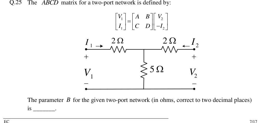
The parameter for the given two-port network (in ohms, correct to two decimal places) is _______.

GATE 2018 EC question 25: A T-network two-port.Tap to open full size
Figure from the GATE 2018 EC paper. It is part of the question.
Figure description

A T-network two-port. Port 1 on the left: top terminal with current I_1 flowing into the network (arrow pointing right), voltage V_1 with + at the top terminal and − at the bottom terminal. Port 2 on the right: top terminal with current I_2 flowing into the network (arrow pointing left), voltage V_2 with + at the top and − at the bottom. Along the top line, a 2 Ω series resistor from the port-1 top terminal to a central node, and a second 2 Ω series resistor from the central node to the port-2 top terminal. A 5 Ω shunt resistor connects the central node down to the common bottom line, which joins the two bottom (−) terminals directly.

Answer and solution
GATE 2018 EC Q.25: answer and solution

GATE 2018 EE Q.19

GATE 2018 · EEQ.19 · 1 mark · NAT

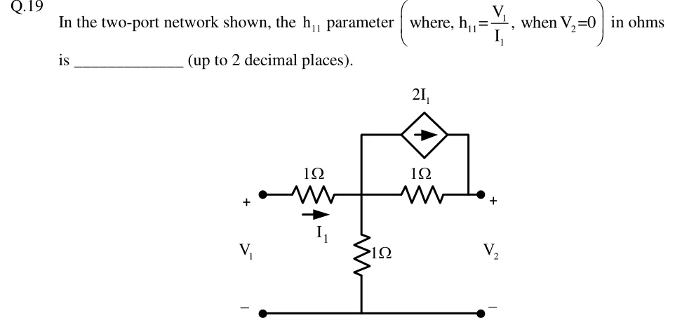
In the two-port network shown, the parameter in ohms is ________ (up to 2 decimal places).

GATE 2018 EE question 19: A two-port network with a common bottom (ground) rail running from the port-1 minus terminal to the port-2 minus terminal.Tap to open full size
Figure from the GATE 2018 EE paper. It is part of the question.
Figure description

A two-port network with a common bottom (ground) rail running from the port-1 minus terminal to the port-2 minus terminal. From the port-1 plus terminal (voltage V_1, + on top, − at the bottom rail), a 1 Ω series resistor runs right to a central node A. Current I_1 flows through this resistor from the port-1 terminal towards node A (arrow pointing right). Node A has three connections: (i) a 1 Ω shunt resistor from node A down to the bottom rail; (ii) a 1 Ω series resistor from node A right to node B, the port-2 plus terminal (voltage V_2, + on top, − at the bottom rail); (iii) a wire rising from node A to a diamond-shaped dependent current source of value 2I_1 (current-controlled by the port-1 current I_1), whose arrow points right, and whose right end drops down to node B. So the 2I_1 source is in parallel with the 1 Ω resistor between A and B and drives current from node A to node B.

Answer and solution
GATE 2018 EE Q.19: answer and solution

PRACTICE

5 questions to test yourself

PRACTICE 11 mark · MCQ

The h-parameters of a two-port are , , and . The network is

  1. (A)

    reciprocal and symmetric

  2. (B)

    reciprocal but not symmetric

  3. (C)

    symmetric but not reciprocal

  4. (D)

    neither reciprocal nor symmetric

Answer and solution

Answer: (A)

  1. Reciprocity needs : , so the network is reciprocal.

  2. Symmetry needs : , so it is symmetric.

  3. Check through : and , equal as expected.

PRACTICE 22 marks · MSQ

The transmission parameters of a two-port, defined by and with entering port 2, are , , and . Which of the following statements is/are correct?

  1. (A)

    The network is reciprocal and symmetric.

  2. (B)

  3. (C)

  4. (D)

    The image impedance of the network is .

Answer and solution

Answer: (A), (B)

  1. , so the network is reciprocal; , so it is symmetric. (A) is correct.

  2. . (B) is correct.

  3. , not . (C) is wrong.

  4. For a symmetric network . The figure is , the short-circuit input impedance. (D) is wrong.

PRACTICE 32 marks · NAT

A two-port has a common lower terminal (the reference); node 1 and node 2 are the upper terminals of ports 1 and 2. The network contains a resistor from node 1 to the reference, a resistor between node 1 and node 2, a resistor from node 2 to the reference, and a voltage-controlled current source between node 2 and the reference that carries a current of amperes ( in volts) from node 2 into the reference. Port 2 is terminated in a resistor. The voltage gain is ______ (rounded to two decimal places).

Answer and solution

Answer: (accepted range )

  1. Nodal equations at the port nodes, with and entering. Node 1: .

  2. Node 2 (the source current leaves the node): .

  3. So , , and (siemens). Since , the network is not reciprocal.

  4. Load: , i.e. . Then .

  5. Direct check at node 2 with the load: gives .

PRACTICE 42 marks · MCQ

A symmetric T section has two series arms of each and a shunt arm of . Two such sections are connected in cascade, and the output port of the combination is left open. The voltage gain of the combination is

  1. (A)

  2. (B)

  3. (C)

  4. (D)

Answer and solution

Answer: (A)

  1. One section: , , , . Check: .

  2. Cascade: .

  3. Output open (): , so .

  4. Direct check: the input sees ; the first shunt node sits at , and the second shunt node at half of that, , which is because the last series arm carries no current.

  5. Option (B), , squares the open-circuit gain of one section and ignores the loading of the first section by the second.

PRACTICE 51 mark · NAT

A reciprocal two-port has , and . Port 2 is terminated in a resistor. The input impedance seen at port 1, in ohms, is ______.

Answer and solution

Answer: (accepted range )

  1. With entering port 2, the load gives .

  2. .

OFFICIAL GATE 2027 SYLLABUS WORDING

Copied from the GATE 2027 syllabus; see all 2027 syllabi.

GATE EC

Linear 2-port network parameters

GATE EE

two port networks

GATE IN

Analysis of one-port and two-port networks with controlled voltage and current sources, driving point impedance and admittance, open and short circuit parameters

Preparing in Kolkata? IAE Academy's course for GATE ECE, GATE EE or GATE IN.