Sinusoidal steady-state analysis replaces the differential equations of an RLC circuit with complex algebra: every source and response becomes a phasor and every element an impedance, so nodal, mesh and the network theorems apply unchanged. On that base sit rms values, the AC power quantities (active, reactive, apparent and complex power, power factor and its correction), maximum power transfer with complex impedances, series and parallel resonance with Q and bandwidth, locus diagrams, and simple RLC filters. Most problems here reduce to a few lines of phasor arithmetic once the right convention (rms phasors, passive sign convention, S=VI∗) and the right formula are chosen.
34 previous-year questions · 34 solved · 6 practice questions
Periodic waveforms: average, rms, form and crest factor
For a periodic signal of period T, the average (dc) value is the mean over one period and the rms (effective) value is the square root of the mean of the square. The rms value is the dc value that would dissipate the same average power in a resistor, which is why meter readings, nameplate ratings and every AC power formula use rms. For waveforms whose full-cycle average is zero (sine, symmetric square, symmetric triangle), the average used in the form factor is the half-cycle average.
AVERAGE VALUE
Vavg=T1∫t0t0+Tv(t)dt
Any periodic waveform; integrate over any one full period.
RMS VALUE
Vrms=T1∫t0t0+Tv2(t)dt
Any periodic waveform. Square first, then average, then take the root.
v=Vmsin(ωt+θ). The full-cycle average is zero; the rms value does not depend on the phase θ.
FORM FACTOR AND CREST (PEAK) FACTOR
kf=VavgVrms,kc=VrmsVpeak
Vavg is the half-cycle average for a waveform whose full-cycle average is zero; Vpeak is the largest absolute value. For a sine, kf=π/(22)≈1.11 and kc=2≈1.414.
Waveform (peak Vm)
Average
RMS
Form factor
Crest factor
Sine Vmsinωt
0 (full cycle); 2Vm/π (half cycle)
Vm/2
1.11
2=1.414
Full-wave rectified sine
2Vm/π
Vm/2
1.11
1.414
Half-wave rectified sine
Vm/π
Vm/2
π/2=1.571
2
Symmetric square, ±Vm
0 (full); Vm (half)
Vm
1
1
Symmetric triangle, ±Vm
0 (full); Vm/2 (half)
Vm/3
2/3=1.155
3=1.732
Sawtooth, 0 to Vm
Vm/2
Vm/3
1.155
1.732
Rectangular pulse train: Vm for a fraction D of each period, 0 otherwise (0<D≤1)
DVm
VmD
1/D
1/D
RMS OF A SUM OF DIFFERENT FREQUENCIES
Vrms=V02+n∑Vn,rms2=V02+n∑2Vmn2
Only when the components have different frequencies (dc counts as frequency zero): products of different frequencies average to zero over the common period. Add same-frequency terms as phasors first.
EXAM TIP
Trap: 10sinωt+10sin(ωt+60∘) is ONE sinusoid of amplitude ∣10∠0∘+10∠60∘∣=17.32, so its rms value is 12.25, not 50+50=10. Squares of rms values add only for different frequencies, or for same-frequency terms exactly 90∘ apart (such as sinωt and cosωt).
WORKED EXAMPLE
Find the rms value of i(t)=5+10sin(100πt)+10sin(100πt+60∘)+4cos(300πt) A.
▸ Solution
The two 100π terms have the same frequency, so add them as peak phasors: 10∠0∘+10∠60∘=15+j8.66=17.32∠30∘. Their rms value is 17.32/2=12.25 A, whose square is 150.
The 300π term has rms value 4/2=2.83 A, square 8. The dc term contributes 52=25.
Different frequencies add in squares: Irms=25+150+8=183.
Answer:Irms=183≈13.53 A
Phasors, impedance and admittance
In a linear, time-invariant circuit driven by sinusoids of one frequency ω, once the transient (natural) response has died out, every voltage and current is a sinusoid of that same frequency; only amplitude and phase differ. A phasor stores those two numbers as one complex number. Convention in these notes: phasors are rms and referred to cosine, so v(t)=2∣V∣cos(ωt+θ)↔V=∣V∣∠θ. Convert a sine with sinx=cos(x−90∘), or take sine as the reference for every source in the problem; mixing references is the error, not the choice. If a problem uses peak phasors, every power expression below that is written in phasor magnitudes (such as ∣V∣∣I∣cosϕ,∣I∣2R,VI∗ and ∣VTh∣2/(4RTh)) gains a factor 21.
Because d/dt becomes multiplication by jω, each element obeys V=ZI with a complex impedance, and KCL, KVL, nodal and mesh analysis, source transformation, superposition, Thevenin and Norton all carry over unchanged with complex arithmetic.
ELEMENT IMPEDANCES
ZR=R,ZL=jωL,ZC=jωC1=−ωCj
Inductor: voltage leads current by 90∘. Capacitor: current leads voltage by 90∘. Resistor: in phase.
IMPEDANCE
Z=R+jX=∣Z∣∠ϕ,∣Z∣=R2+X2,ϕ=tan−1RX
X>0: inductive, current lags. X<0: capacitive, current leads. ϕ is the angle by which voltage leads current. The arctangent form assumes R>0 (a passive impedance); for R=0,ϕ=+90∘ or −90∘ with the sign of X.
ADMITTANCE
Y=Z1=G+jB,G=R2+X2R,B=R2+X2−X
G=1/R only when X=0. Susceptances: capacitor BC=ωC>0, inductor BL=−1/(ωL)<0.
Same as dc, with complex numbers: the voltage divider is for elements in series, the current divider for two parallel branches. Magnitudes add only when the phasors are in phase.
Phasor-domain analysis, in order
Check that every source has the same ω. Choose one reference (cos or sin) and one scale (rms or peak), and write each source as a phasor.
Replace R, L, C by R,jωL,1/(jωC); a mutual inductance by jωM, signed by the dot convention (a current entering the dotted terminal of one coil induces a voltage in the other coil that is positive at that coil's dotted terminal).
Solve with nodal or mesh analysis, Thevenin/Norton, source transformation or superposition, in complex algebra.
Convert back: the rms phasor ∣V∣∠θ gives v(t)=2∣V∣cos(ωt+θ).
If the sources have different frequencies, solve one circuit per frequency (the impedances change with ω) and add the responses in the time domain. Never add phasors of different frequencies.
A phasor diagram draws these complex numbers to scale. Take the quantity common to all elements as the reference: current in a series circuit, voltage in a parallel one. In series RLC the drops VR (in phase with I),VL (90∘ ahead of I) and VC (90∘ behind I) add as vectors, ∣V∣=VR2+(VL−VC)2, so a single element voltage can exceed the supply voltage.
EXAM TIP
Meter readings are magnitudes. In a series RL circuit with VR=60 V and VL=80 V, the supply is 602+802=100 V, not 140 V. KVL holds for phasors, not for voltmeter readings.
AC power: active, reactive, apparent and complex
Convention: passive sign convention (current enters the + terminal of the element), so a positive result is power absorbed; phasors are rms. For a load with V=∣V∣∠θv and I=∣I∣∠θi, the power-factor angle is ϕ=θv−θi, which equals the angle of the load impedance.
INSTANTANEOUS POWER
p(t)=v(t)i(t)=∣V∣∣I∣cosϕ+∣V∣∣I∣cos(2ωt+θv+θi)
With v=2∣V∣cos(ωt+θv) and i=2∣I∣cos(ωt+θi): a constant plus a term at 2ω whose average is zero.
rms values. P is the average of p(t).Q is the amplitude of the part of p(t) that flows back and forth between the source and the fields of L and C, with zero average.
COMPLEX POWER
S=VI∗=P+jQ=∣I∣2Z=Z∗∣V∣2
rms phasors, power absorbed by the load. With peak phasors, S=21VmIm∗. The conjugate goes on the current; writing V∗I instead flips the sign of Q.
XL=ωL and XC=1/(ωC) are positive magnitudes. An inductor absorbs reactive power, a capacitor delivers it, and neither absorbs average power.
POWER FACTOR
pf=cosϕ=∣S∣P=∣Z∣R
Lagging when current lags voltage (ϕ>0,Q>0, inductive); leading when current leads (ϕ<0,Q<0, capacitive); unity at ϕ=0. Always state lagging or leading with the number.
CONSERVATION OF COMPLEX POWER
all elements∑Sk=0⇒∑Pdelivered=∑Pabsorbed,∑Qdelivered=∑Qabsorbed
Every element taken with the passive sign convention. P and Q of loads add whether they are in series or parallel; apparent powers ∣S∣ do NOT add in general (only when every load has the same power-factor angle).
Power-factor correction. A lagging load draws more current than its real power needs, which raises line I2R loss and the kVA rating the supply must provide. A capacitor connected in parallel (so the load voltage is unchanged) supplies part of the load's reactive power: P is unchanged, the reactive power drawn from the supply falls, and so does the supply current.
SHUNT CAPACITOR FOR PF CORRECTION
QC=P(tanϕ1−tanϕ2),C=ω∣V∣2P(tanϕ1−tanϕ2)
ϕ1,ϕ2 = pf angles before and after (lagging taken positive), ∣V∣ = rms voltage across the capacitor, P in W. For a final leading pf take ϕ2 negative.
WORKED EXAMPLE
A single-phase load takes 10 kW at 0.8 pf lagging from a 230 V (rms), 50 Hz supply. Find the shunt capacitance that raises the supply pf to 0.95 lagging, and the supply current before and after.
▸ Solution
tanϕ1=tan(cos−10.8)=0.75, so Q1=10000×0.75=7500 var.
tanϕ2=tan(cos−10.95)=0.3287, so Q2=10000×0.3287=3287 var.
Supply current before: ∣S1∣/∣V∣=(10000/0.8)/230=54.3 A. After: (10000/0.95)/230=45.8 A. P is the same 10 kW in both cases.
Answer:C≈253.5μF; the supply current falls from 54.3 A to 45.8 A.
Non-sinusoidal periodic waveforms. Expand v and i into dc plus harmonics. The product of two sinusoids of different frequencies averages to zero over the common period, so average power comes only from voltage and current terms of the same frequency.
AVERAGE POWER WITH HARMONICS
P=V0I0+n=1∑∞VnIncosϕn
Vn,In = rms values of the n-th harmonic; ϕn = angle by which Vn leads In. A harmonic present in only one of v,i contributes nothing. Power factor =P/(VrmsIrms) using the full rms values. If v is a pure sinusoid and only i is distorted, this becomes pf=(I1/Irms)cosϕ1: distortion factor times displacement factor.
WORKED EXAMPLE
A two-terminal network (passive sign convention) has v(t)=100+1002sinωt+502sin3ωt V and i(t)=5+102sin(ωt−60∘)+22sin5ωt A. Find the average power and the power factor.
▸ Solution
dc: 100×5=500 W.
Fundamental: rms values 100 V and 10 A, voltage leading current by 60∘:100×10×cos60∘=500 W.
The 3rd harmonic is only in v and the 5th only in i, so neither contributes. P=1000 W.
Vrms=1002+1002+502=150 V; Irms=52+102+22=129=11.36 A.
pf=150×11.361000=0.587.
Answer:P=1000 W; pf ≈0.587
EXAM TIP
Quick checks: a pure L or C absorbs P=0. For loads in parallel, add the P's and the Q's separately and only then take ∣S∣=P2+Q2. A capacitor rated QC at voltage V and frequency f delivers QC(V′/V)2(f′/f) at voltage V′ and frequency f′, because its reactive power is ∣V∣2ωC.
Maximum power transfer in AC
Replace the network seen by the load with its Thevenin equivalent: VTh (rms) in series with ZTh=RTh+jXTh.VTh is the open-circuit voltage at the load terminals; ZTh=Voc/Isc, or the ratio V/I at the terminals when a test source is applied with every independent source set to zero (the test-source method is needed when dependent sources are present). For a load ZL=RL+jXL the load current is VTh/(ZTh+ZL), and what maximises the load power depends on which parts of ZL are allowed to vary.
LOAD POWER
PL=(RTh+RL)2+(XTh+XL)2∣VTh∣2RL
VTh rms. Start every restricted-load problem from this expression.
What the load may vary
Condition for maximum
Maximum load power
RL and XL both free
ZL=ZTh∗:RL=RTh,XL=−XTh
4RTh∣VTh∣2
Purely resistive load (XL=0)
RL=∣ZTh∣=RTh2+XTh2
Substitute into PL
RL free, XL fixed
RL=RTh2+(XTh+XL)2
Substitute into PL
XL free, RL fixed
XL=−XTh
(RTh+RL)2∣VTh∣2RL
Angle of ZL fixed, ∣ZL∣ free
∣ZL∣=∣ZTh∣
Substitute into PL
CONJUGATE MATCH
ZL=ZTh∗⇒PL,max=4RTh∣VTh∣2
rms VTh (with a peak value VTh,m it is VTh,m2/(8RTh)). The Thevenin source then delivers twice this power, so the efficiency measured against the Thevenin equivalent is 50%.
PURELY RESISTIVE LOAD
RL=∣ZTh∣=RTh2+XTh2
When the load cannot have reactance. Gives less power than the conjugate match unless XTh=0.
WORKED EXAMPLE
A network has VTh=50∠0∘ V (rms) and ZTh=3+j4Ω at the operating frequency. Find the maximum load power (a) for an arbitrary load impedance and (b) for a purely resistive load.
▸ Solution
(a) Conjugate match, ZL=3−j4Ω:Pmax=4×3502=208.3 W.
(b) RL=∣ZTh∣=5Ω. Current ∣I∣=∣8+j4∣50=8050=5.59 A.
P=∣I∣2RL=802500×5=156.25 W.
Answer: (a) 208.3 W with ZL=3−j4Ω; (b) 156.25 W with RL=5Ω
EXAM TIP
With a purely resistive load, do not set RL=RTh when XTh=0; the optimum is RL=∣ZTh∣. And a conjugate match holds at one frequency only, because the load reactance must cancel XTh at that ω.
EXAM TIP
Two more traps. (1) If the load is fixed and the source resistance RTh is what can be adjusted, PL is largest at the smallest possible RTh (zero if allowed), not at RTh=RL: every matching condition above assumes a fixed source and an adjustable load. (2) An ideal transformer of turns ratio N1:N2, with the network on the N1 side, presents the load to the network as (N1/N2)2ZL. It scales ∣ZL∣ but not its angle, so it is the 'angle fixed, ∣ZL∣ free' case: for a resistive load choose (N1/N2)2RL=∣ZTh∣, which is RTh when ZTh is resistive.
Resonance: series, parallel and the practical tank
A circuit containing both L and C is resonant at the frequency where its input impedance (equivalently admittance) is purely real, so the source voltage and current are in phase (unity pf). The net reactive power absorbed, 2ω(Wˉm−Wˉe) with Wˉm and Wˉe the time-averaged energies stored in the inductors and in the capacitors, is then zero: the reactive powers of L and C cancel, and energy swaps between L and C instead of between the circuit and the source. In this section Q denotes the quality factor, not reactive power.
RESONANT FREQUENCY
ω0=LC1,f0=2πLC1
Ideal series RLC and ideal parallel RLC (frequency-independent R). The value of R does not shift it.
Series RLC, Z=R+j(ωL−1/(ωC)): at ω0,∣Z∣=R is minimum and the current V/R is maximum. Below ω0 the circuit is capacitive (current leads); above ω0 it is inductive (current lags).
QUALITY FACTOR, SERIES RLC
Q=Rω0L=ω0CR1=R1CL
R is the total series resistance, including the coil's own resistance and the source's internal resistance.
QUALITY FACTOR, GENERAL DEFINITION
Q=2πenergy dissipated per cyclemaximum energy stored
Evaluated at resonance, counting the total energy stored in L and C; it reduces to the series and parallel formulas.
VOLTAGE MAGNIFICATION (SERIES)
∣VL∣=∣VC∣=Q∣V∣at ω0
The L and C voltages are 180∘ apart and cancel, but each is Q times the supply voltage.
HALF-POWER FREQUENCIES (SERIES)
ω1,2=∓2LR+(2LR)2+LC1,ω0=ω1ω2
Constant-amplitude voltage source. At ω1 and ω2:∣I∣=Imax/2,P=Pmax/2,∣Z∣=2R, impedance angle −45∘ at ω1 (capacitive) and +45∘ at ω2 (inductive). ω0 is their exact geometric mean.
BANDWIDTH (SERIES)
BW=ω2−ω1=LRrad/s=Qω0,in Hz: 2πLR=Qf0
Exact for any Q. For high Q (roughly Q≥10),ω1,2≈ω0∓BW/2; the arithmetic symmetry about ω0 is only approximate, the geometric one is exact.
FREQUENCIES OF PEAK CAPACITOR AND INDUCTOR VOLTAGE (SERIES)
ωC,max=ω01−2Q21,ωL,max=1−2Q21ω0
Constant-amplitude source, Q>1/2.VC peaks slightly below ω0 and VL slightly above, both at the same height ∣VC∣max=∣VL∣max=Q∣V∣/1−1/(4Q2), a little above Q∣V∣. The current and VR peak exactly at ω0.
WORKED EXAMPLE
A series RLC circuit has R=10Ω,L=0.1 H, C=10μF and is fed from a 50 V (rms) variable-frequency source. Find ω0,Q, the bandwidth, the half-power frequencies, and the current and capacitor voltage at resonance.
Q=ω0L/R=100/10=10;BW=R/L=100 rad/s, which equals ω0/Q.
ω1,2=∓50+502+106=∓50+1001.25, so ω1=951.25 rad/s and ω2=1051.25 rad/s. Check: ω1ω2=106=ω02.
At resonance I=50/10=5 A and P=52×10=250 W.
∣VC∣=∣VL∣=QV=500 V. Check: I/(ω0C)=5/(1000×10−5)=500 V.
Answer:ω0=1000 rad/s, Q=10, BW =100 rad/s, ω1=951.25 rad/s, ω2=1051.25 rad/s, I=5 A, ∣VC∣=500 V
Parallel RLC (ideal R, L and C in parallel, Y=G+j(ωC−1/(ωL))) is the dual: at ω0 the admittance is minimum, the impedance is maximum and equal to R, and the current drawn from a voltage source is minimum (V/R); fed from a current source, the voltage is maximum. Below ω0 the circuit is inductive and above it capacitive, the opposite of series.
QUALITY FACTOR AND BANDWIDTH, PARALLEL RLC
Q=ω0LR=ω0CR=RLC,BW=RC1rad/s=Qω0
Ideal parallel RLC. Current magnification: at ω0,∣IL∣=∣IC∣=Q∣Isource∣. A current source with internal resistance Rs puts Rs in parallel with R: use R∥Rs in Q and BW.
HALF-POWER FREQUENCIES (PARALLEL)
ω1,2=∓2RC1+(2RC1)2+LC1
Ideal parallel RLC driven by a constant-amplitude current source, so ∣V∣=∣V∣max/2 there; again ω0=ω1ω2.
A series Rs+jXs and a parallel combination of Rp and jXp have the same impedance at the frequency where the values are computed, and only there. For Q≫1,Rp≈Q2Rs and Xp≈Xs, which is where the tank result ZD≈Q2R below comes from.
Practical tank circuit. A real coil has series resistance, so the usual tank is a coil (R in series with L) in parallel with C. Setting the imaginary part of Y=jωC+R+jωL1 to zero gives the unity-pf frequency and the purely resistive impedance there.
PRACTICAL TANK (COIL R, L IN PARALLEL WITH C)
ω0=LC1−L2R2,ZD=CRL
ω0 = frequency of unity pf; ZD = dynamic impedance (purely resistive) at that frequency. A real ω0 exists only if R<L/C. Exactly, ZD=R(1+Q2) with the coil Q=ω0L/R taken at this ω0; for Q≫1,ω0≈1/LC and ZD≈Q2R.
Property
Series RLC
Parallel RLC (ideal)
∣Z∣ at ω0
minimum, =R
maximum, =R
Current from a voltage source at ω0
maximum, V/R
minimum, V/R
Magnification at ω0
voltage: ∣VL∣=∣VC∣=QV
current: ∣IL∣=∣IC∣=QI
Q
ω0L/R
R/(ω0L)
Bandwidth (rad/s)
R/L
1/(RC)
Below ω0
capacitive (leading)
inductive (lagging)
Above ω0
inductive (lagging)
capacitive (leading)
Larger R
lower Q, wider BW
higher Q, narrower BW
Selectivity is the ability to pass a narrow band around ω0 and reject nearby frequencies. It rises with Q, since BW=ω0/Q.
Locus diagrams trace the tip of a phasor as one parameter varies. The impedance of a series circuit with one varying element moves along a straight line; the admittance, and so the current for a fixed voltage, is the inverse of a line that misses the origin, which is a circle through the origin. In a parallel circuit whose varying element is a branch on its own, the roles swap: the admittance, and so the current, moves along a straight line.
Standard loci (supply voltage V at angle 0°, held fixed)
Series R-L, R varied from 0 to ∞,XL fixed: I traces a semicircle of diameter V/XL in the lagging (fourth) quadrant, from (V/XL)∠−90∘ at R=0 to the origin.
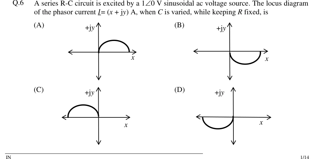
Series R-C, R varied: the same kind of semicircle, diameter V/XC, in the leading (first) quadrant, from (V/XC)∠90∘ at R=0 to the origin.
Series R-L, XL varied from 0 to ∞,R fixed: semicircle of diameter V/R, from (V/R)∠0∘ to the origin, lagging.
Series RLC, ω varied from 0 to ∞:Z moves up the vertical line ReZ=R, and I traces the full circle of diameter V/R through the origin: the leading half below ω0,(V/R)∠0∘ at ω0, the lagging half above, with the half-power points at ±45∘ on it.
R-L branch in parallel with a variable capacitor: I=IRL+jωCV, so the supply current moves along a vertical straight line, starting from the fixed branch current IRL at C=0 and rising as C increases. It is smallest, and in phase with V, where that line crosses the real axis.
On the R-varied locus of a series circuit, the active power ∣V∣∣I∣cosϕ is largest at the point with the largest component in phase with V, where R=X and ϕ=±45∘: maximum power transfer (RL=∣ZTh∣ with a purely reactive ZTh) seen geometrically.
EXAM TIP
For the practical tank, the unity-pf frequency, the frequency of maximum impedance and 1/LC are three slightly different frequencies that coincide only as R→0. A question that says 'in phase' or 'unity power factor' wants ω0=1/(LC)−R2/L2.
EXAM TIP
Increasing R has opposite effects: it lowers Q in a series circuit but raises Q in an ideal parallel circuit. Remember Qseries=X/R and Qparallel=R/X, with X the reactance of L (or C) at ω0.
Passive filters with R, L and C
A filter's transfer function is H(jω)=Vout/Vin, with the output open-circuited unless a load is stated. The cut-off (corner, −3 dB, half-power) frequency is where ∣H∣ falls to 1/2 of its pass-band value: the dc gain for a low-pass, the high-frequency gain for a high-pass, the peak for a band-pass. (A second-order low-pass with Q>1/2 peaks above its dc gain; its cut-off is still measured from the dc gain.) Identify the type from the limits: as ω→0 a capacitor is an open circuit and an inductor a short circuit; as ω→∞ the reverse.
FIRST-ORDER LOW-PASS
H(jω)=1+jω/ωc1,ωc=RC1(series R, output across C) or LR(series L, output across R)
Match the denominator to read ω0 and Q directly: series RLC has ω0/Q=R/L, parallel RLC has ω0/Q=1/(RC). Damping ratio ζ=1/(2Q). The band-pass and band-stop bandwidth is ω0/Q. Asymptotic slopes: low-pass −40 dB/decade above ω0, high-pass +40 dB/decade below it, band-pass ±20 dB/decade on its two skirts.
CUT-OFF OF THE SECOND-ORDER LOW-PASS
(ω0ωc)2=(1−2Q21)+(1−2Q21)2+1
−3 dB point relative to the dc gain. Q=1/2 (maximally flat) gives ωc=ω0. For the matching high-pass, ωc,HP=ω02/ωc,LP.
WORKED EXAMPLE
An RC high-pass filter (series C, output across R, no load) has R=2kΩ and C=0.1μF. Find the cut-off frequency, and the gain magnitude and phase at twice that frequency.
▸ Solution
ωc=1/(RC)=1/(2000×10−7)=5000 rad/s, so fc=5000/(2π)=795.8 Hz.
At ω=2ωc:H=1+j2j2,∣H∣=52=0.894 (about −0.97 dB).
Phase =90∘−tan−12=90∘−63.43∘=26.57∘; the output leads the input.
Answer:fc≈795.8 Hz; at 2fc,∣H∣≈0.894 and phase ≈+26.6∘
EXAM TIP
Loading changes a filter. A resistor Rload across C in an RC low-pass makes the dc gain Rload/(R+Rload) and the cut-off ωc=1/(C(R∥Rload)). Take the Thevenin equivalent at the capacitor terminals instead of using the unloaded formula.
EXAM TIP
Identify a filter quickly: open every C and short every L to get the ω→0 output, then short every C and open every L for ω→∞. Output only at dc: low-pass. Only at high frequency: high-pass. Zero at both ends: band-pass. Non-zero at both ends with a null at one frequency: band-stop (notch).
PREVIOUS-YEAR QUESTIONS
34 questions from the EC, EE and IN papers
Try each question first, then open the answer. We placed each question under a topic ourselves; the exam paper does not label topics.
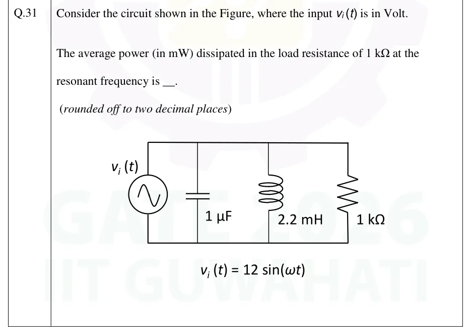
Consider the circuit shown in the Figure, where the input vi(t) is in Volt.
The average power (in mW) dissipated in the load resistance of 1kΩ at the resonant frequency is ____. (rounded off to two decimal places)
vi(t)=12sin(ωt)
Tap to open full sizeFigure from the GATE 2026 EC paper. It is part of the question.Figure description
An ideal sinusoidal voltage source v_i(t) (circle with a sine symbol) sits in the left vertical branch. Its top terminal connects to a top rail and its bottom terminal to a bottom rail. Three more vertical branches run between the same two rails, left to right: a 1 capacitor, a 2.2 mH inductor and a 1 k Ω resistor. There are no other elements, so the source, C, L and R are all in parallel across the same two nodes. Below the circuit it reads: v_i(t) = 12 sin (ω t).
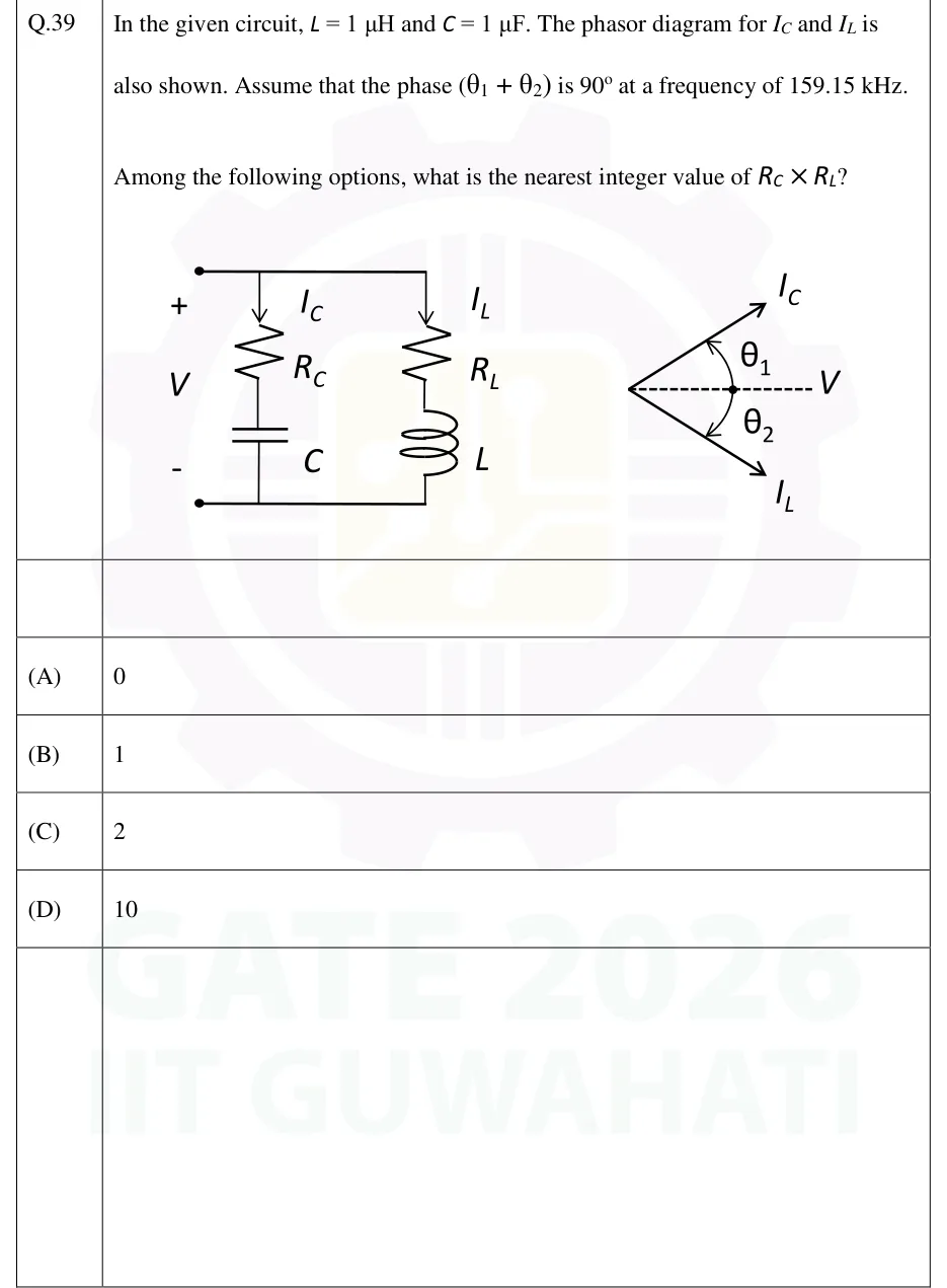
In the given circuit, L=1μH and C=1μF. The phasor diagram for IC and IL is also shown. Assume that the phase (θ1+θ2) is 90∘ at a frequency of 159.15 kHz.
Among the following options, what is the nearest integer value of RC×RL?
Tap to open full sizeFigure from the GATE 2026 EC paper. It is part of the question.Figure description
Left: a voltage V is applied across two terminals, + at the top and - at the bottom. Two branches are connected in parallel across these terminals. Branch 1: current I_C flows downward through resistor R_C in series with capacitor C. Branch 2: current I_L flows downward through resistor R_L in series with inductor L. Right: phasor diagram with V as the horizontal dashed reference pointing right. I_C is drawn above the reference, leading V by angle θ_1. I_L is drawn below the reference, lagging V by angle θ_2.
Tap to open full sizeFigure from the GATE 2026 IN paper. It is part of the question.Figure description
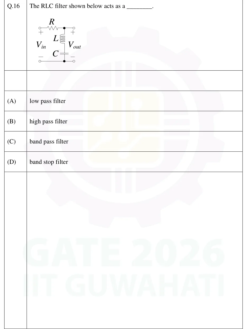
Two-port RLC network. The input terminals are on the left, marked V_in (+ at top, - at bottom). A resistor R runs in series along the top rail from the V_in + terminal to a junction node (marked with a dot). From that junction the top rail continues straight to the V_out + terminal on the right. A series branch of an inductor L (upper) and a capacitor C (lower) runs from the junction node down to the bottom rail. The bottom rail is a plain wire from the V_in - terminal to the V_out - terminal and joins the lower end of the capacitor at a node (marked with a dot). V_out (+ at top, - at bottom) is therefore taken across the series L-C branch, with the output terminals open (no load).
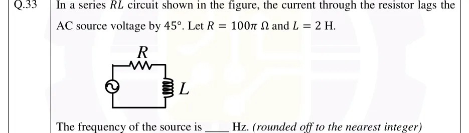
In a series RL circuit shown in the figure, the current through the resistor lags the AC source voltage by 45∘. Let R=100πΩ and L=2H.
The frequency of the source is ____ Hz. (rounded off to the nearest integer)
Tap to open full sizeFigure from the GATE 2026 IN paper. It is part of the question.Figure description
A single-loop series circuit. An AC voltage source (a circle with a sine symbol) is on the left side of the loop. A resistor labelled R is on the top wire. An inductor (a coil) labelled L is on the right side. A plain wire along the bottom closes the loop back to the source. The figure shows only the symbols R and L. Their values are given in the stem. Source, R and L are all in series, so the same current flows through all three.
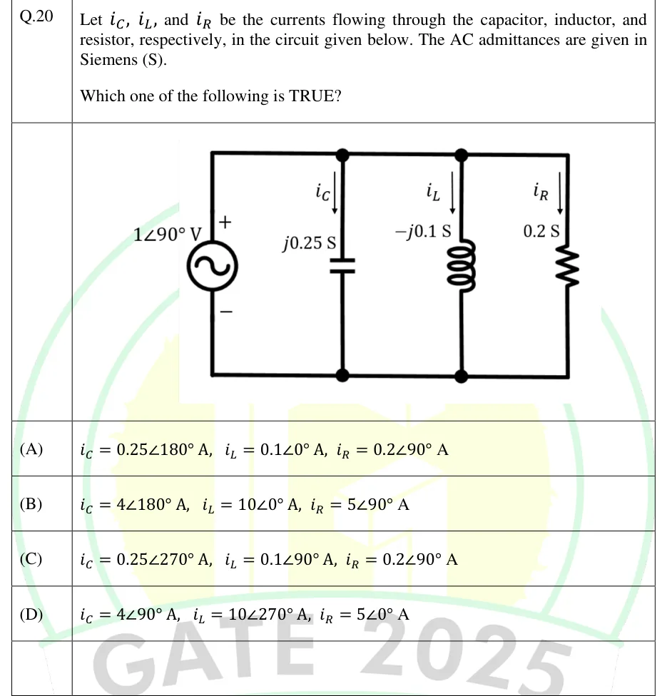
Let iC,iL, and iR be the currents flowing through the capacitor, inductor, and resistor, respectively, in the circuit given below. The AC admittances are given in Siemens (S).
Which one of the following is TRUE?
Tap to open full sizeFigure from the GATE 2025 EC paper. It is part of the question.Figure description
A voltage source 1 ∠ 90° V on the left (+ terminal at top, − at bottom) connects between a top rail and a bottom rail. Three branches are connected in parallel between these rails, from left to right: (1) a capacitor labelled j0.25 S, current i_C arrowed downward (top rail to bottom rail); (2) an inductor labelled -j0.1 S, current i_L arrowed downward; (3) a resistor labelled 0.2 S, current i_R arrowed downward. Junction dots mark where the capacitor and inductor branches meet the top and bottom rails. The source and the resistor branch join at the left and right corners of the rails.
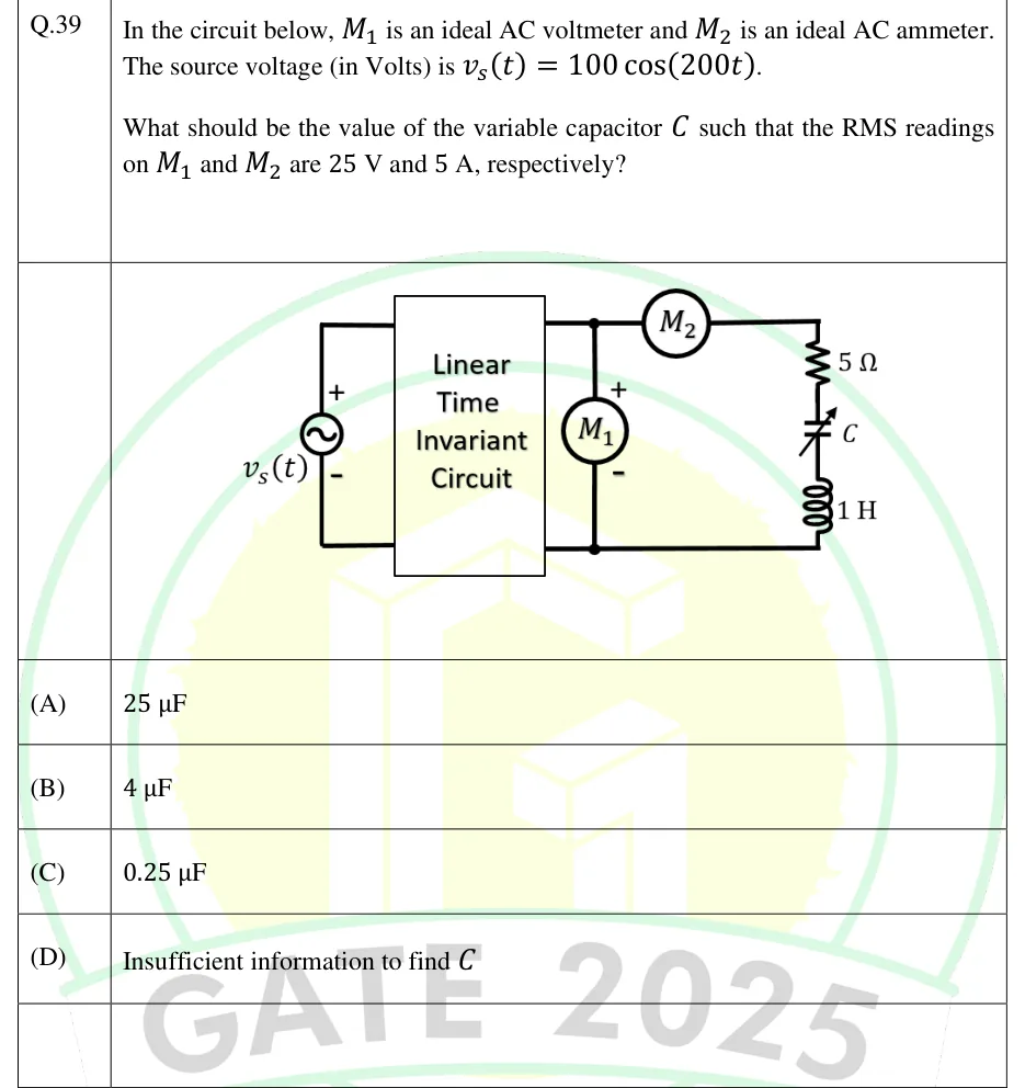
In the circuit below, M1 is an ideal AC voltmeter and M2 is an ideal AC ammeter. The source voltage (in Volts) is vs(t)=100cos(200t).
What should be the value of the variable capacitor C such that the RMS readings on M1 and M2 are 25 V and 5 A, respectively?
Tap to open full sizeFigure from the GATE 2025 EC paper. It is part of the question.Figure description
A sinusoidal voltage source v_s(t) (+ terminal at top, - at bottom) is connected to the left-hand input terminals of a two-port box labelled "Linear Time Invariant Circuit". The box's right-hand output terminals form a top node and a bottom node. The ideal AC voltmeter M_1 is connected directly between these two output nodes (+ at the top node, - at the bottom node). From the top node, the ideal AC ammeter M_2 is in series along the top wire, feeding a series branch that runs down the right side: a 5 Ω resistor, then a variable capacitor C, then a 1 H inductor, returning to the bottom node. So M_1 reads the voltage across the whole series R-C-L branch and M_2 reads the current through it.
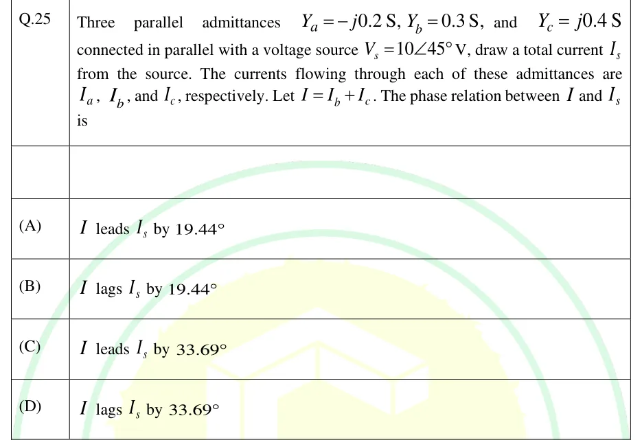
Three parallel admittances Ya=−j0.2S,Yb=0.3S, and Yc=j0.4S connected in parallel with a voltage source Vs=10∠45∘V, draw a total current Is from the source. The currents flowing through each of these admittances are Ia,Ib, and Ic, respectively. Let I=Ib+Ic. The phase relation between I and Is is
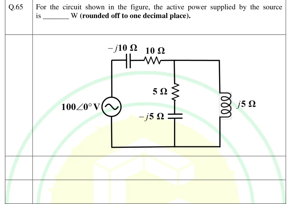
For the circuit shown in the figure, the active power supplied by the source is ________ W (rounded off to one decimal place).
Tap to open full sizeFigure from the GATE 2025 IN paper. It is part of the question.Figure description
A sinusoidal voltage source 100 ∠ 0° V sits on the left vertical side. No polarity marks are printed. From the top of the source, a series capacitor -j10 Ω and then a series resistor 10 Ω run along the top wire to node A. From node A, two branches go down to the bottom wire, which returns to the bottom of the source: (1) a middle vertical branch with a 5 Ω resistor in series with a capacitor -j5 Ω (resistor above, capacitor below); (2) a right vertical branch with an inductor j5 Ω. The two vertical branches are in parallel between node A and the bottom wire.
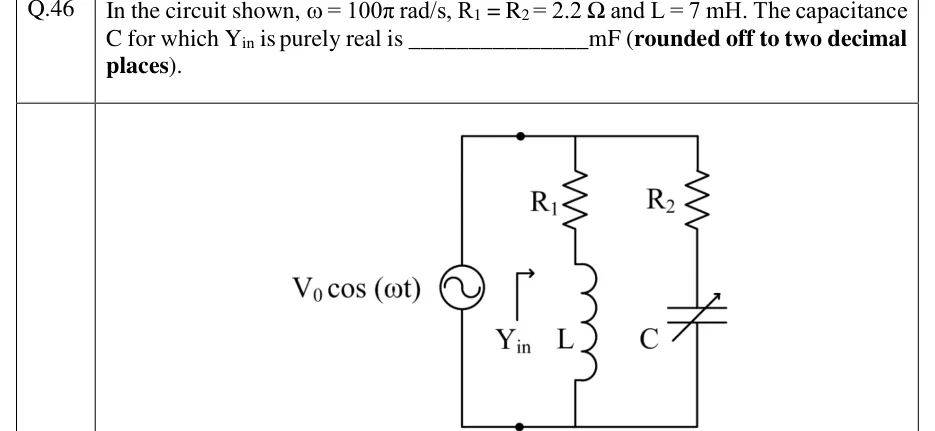
In the circuit shown, ω=100π rad/s, R1=R2=2.2Ω and L=7 mH. The capacitance C for which Yin is purely real is ________ mF (rounded off to two decimal places).
Tap to open full sizeFigure from the GATE 2023 IN paper. It is part of the question.Figure description
An AC voltage source V_0 cos (ω t) sits on the left vertical wire between a top rail and a bottom rail. Two dots, one on the top rail and one on the bottom rail just right of the source, mark the input terminals; an arrow labelled Y_in points into the network to their right. Two branches are connected in parallel between the top and bottom rails. Branch 1 (middle): resistor R_1 in series with inductor L, with R_1 at the top and L below it. Branch 2 (right): resistor R_2 in series with a variable capacitor C (drawn with a diagonal arrow), with R_2 at the top and C below it. So the source sees (R_1 + j ω L) in parallel with (R_2 + 1/(j ω C)).
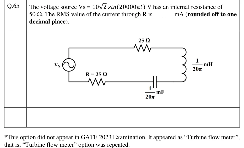
The voltage source Vs = 102sin(20000πt) V has an internal resistance of 50 Ω. The RMS value of the current through R is ______ mA (rounded off to one decimal place).
Tap to open full sizeFigure from the GATE 2023 IN paper. It is part of the question.Figure description
A single series loop. On the left is an AC voltage source labelled Vs (circle with a sine symbol). Starting from the top terminal of the source, the top wire runs right through a 25 Ω resistor and then down the right side through an inductor labelled (1/20π) mH. The bottom wire runs back left from the inductor through a capacitor labelled (1/20π) mF, then through a resistor labelled R = 25 Ω, and back to the bottom terminal of the source. So the source, 25 Ω, the (1/20π) mH inductor, the (1/20π) mF capacitor and R = 25 Ω are all in series. The source's 50 Ω internal resistance is given in the text and is not drawn.
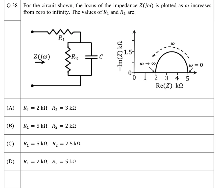
For the circuit shown, the locus of the impedance Z(jω) is plotted as ω increases from zero to infinity. The values of R1 and R2 are:
Tap to open full sizeFigure from the GATE 2022 EC paper. It is part of the question.Figure description
Left: a two-terminal network seen from the input, labelled Z(j ω) with an arrow pointing into it. From the top input terminal, resistor R_1 runs in series to a node; between that node and the bottom input terminal (a plain wire back to the bottom terminal) are two branches in parallel: resistor R_2 and capacitor C. So Z = R_1 + (R_2 C). Right: impedance locus plot with horizontal axis Re(Z) in k Ω (ticks 0, 1, 2, 3, 4, 5) and vertical axis -Im(Z) in k Ω (ticks 0 and 1.5). The locus is a semicircle above the real axis, starting at Re(Z) = 5 k Ω (labelled ω = 0) and ending at Re(Z) = 2 k Ω (labelled ω → ∞), with its top at -Im(Z) = 1.5 k Ω; a dashed arrow labelled ω runs along the arc from the right end to the left end, showing the direction of increasing ω.
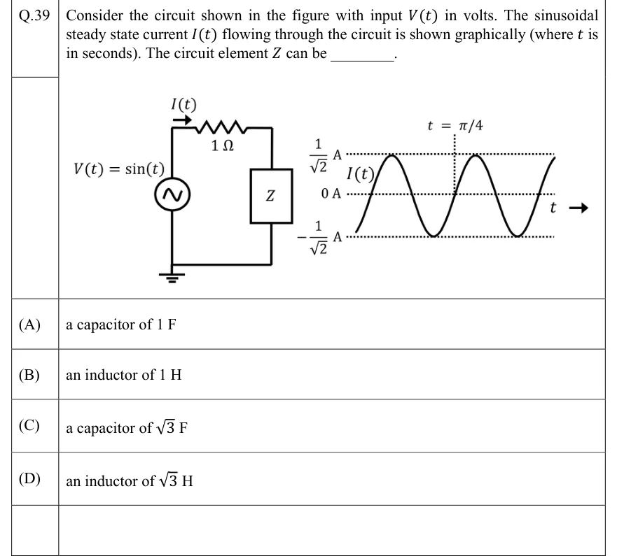
Consider the circuit shown in the figure with input V(t) in volts. The sinusoidal steady state current I(t) flowing through the circuit is shown graphically (where t is in seconds). The circuit element Z can be ________.
Tap to open full sizeFigure from the GATE 2022 EC paper. It is part of the question.Figure description
Left: a single series loop. An AC voltage source labelled V(t) = sin (t) sits on the left branch, and the bottom-left node is connected to ground. From the top of the source a wire runs right through a 1 Ω resistor, then down through a box labelled Z on the right branch, then back along the bottom wire to the source. An arrow above the top wire, at its left end just before the resistor, points right and is labelled I(t), so the current flows clockwise (source top → resistor → Z → bottom). Right: a plot of I(t) against t, with an arrow labelled t pointing right. The origin t = 0 is not marked. Horizontal dotted reference lines are drawn at 1 √ 2 A, 0 A and - 1 √ 2 A. The current is a sinusoid that just touches ± 1 √ 2 A. It is drawn from just above a trough at the left edge to just before a peak at the right edge, a little over two cycles. A vertical dotted line labelled t = π /4 meets the 0 A line exactly where the current crosses zero going UPWARD: the rising zero crossing that follows the first full trough and comes before the second peak.
An inductor having a Q-factor of 60 is connected in series with a capacitor having a Q-factor of 240. The overall Q-factor of the circuit is ________. (round off to nearest integer)
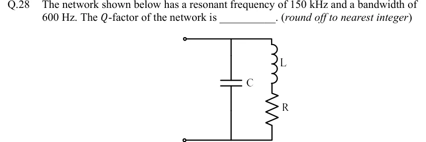
The network shown below has a resonant frequency of 150 kHz and a bandwidth of 600 Hz. The Q-factor of the network is ________. (round off to nearest integer)
Tap to open full sizeFigure from the GATE 2022 EE paper. It is part of the question.Figure description
A two-terminal network with input terminals at top-left and bottom-left (open circles). The top rail runs from the top terminal to the right; the bottom rail runs from the bottom terminal to the right. Between the rails there are two parallel branches: (1) a capacitor C connected directly from the top rail to the bottom rail; (2) to its right, a series branch of an inductor L (upper) followed by a resistor R (lower), connected from the top rail to the bottom rail. So the network is C in parallel with the series combination of L and R (a practical parallel tank circuit). No numerical element values are given.
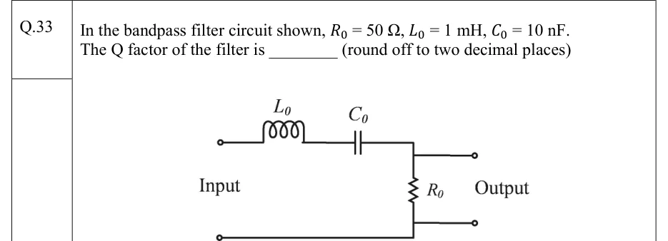
In the bandpass filter circuit shown, R0=50Ω,L0=1mH,C0=10nF. The Q factor of the filter is ________ (round off to two decimal places)
Tap to open full sizeFigure from the GATE 2022 IN paper. It is part of the question.Figure description
Two-port circuit, input terminals on the left, output terminals on the right. From the upper input terminal, an inductor L_0 and a capacitor C_0 are connected in series along the top wire, in that order from left to right. After C_0 the top wire meets a vertical resistor R_0, which runs down to the bottom wire. The bottom wire is common from the lower input terminal to the lower output terminal. The output terminals are taken directly across R_0 (upper output from the top of R_0, lower output from its bottom). Labels: 'Input' on the left, 'Output' on the right. So it is a series R-L-C loop with the output voltage across the resistor.
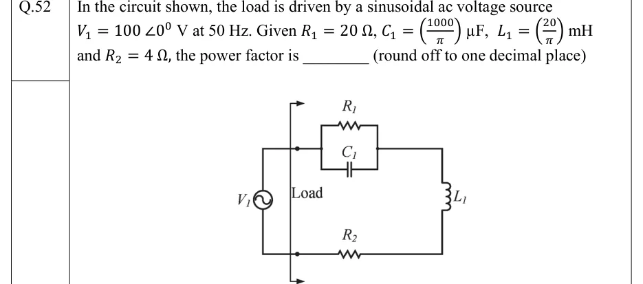
In the circuit shown, the load is driven by a sinusoidal ac voltage source V1=100∠0∘V at 50 Hz. Given R1=20Ω,C1=(π1000)μF, L1=(π20)mH and R2=4Ω, the power factor is ________ (round off to one decimal place)
Tap to open full sizeFigure from the GATE 2022 IN paper. It is part of the question.Figure description
A single-loop circuit. On the left, an ac voltage source V1 (circle with sine symbol) connected between a top wire and a bottom wire. A vertical line with arrowheads at its top and bottom ends, labelled 'Load', marks the boundary just to the right of the source: everything to its right is the load. Top branch (going right from the source): R1 and C1 connected in parallel with each other (R1 drawn above, C1 below), forming one block in the top wire. Right vertical side: inductor L1, connecting the top wire down to the bottom wire. Bottom branch: resistor R2 in the bottom wire, returning to the source. So the load is (R1 || C1) in series with L1 and R2, directly across V1.
A 1 kHz sine-wave generator having an internal resistance of 50 Ω generates an open-circuit voltage of 10 Vp-p. When a capacitor is connected across the output terminals, the voltage drops to 8 Vp-p. The capacitance of the capacitor (in microfarads) is _______ (round off to two decimal places)
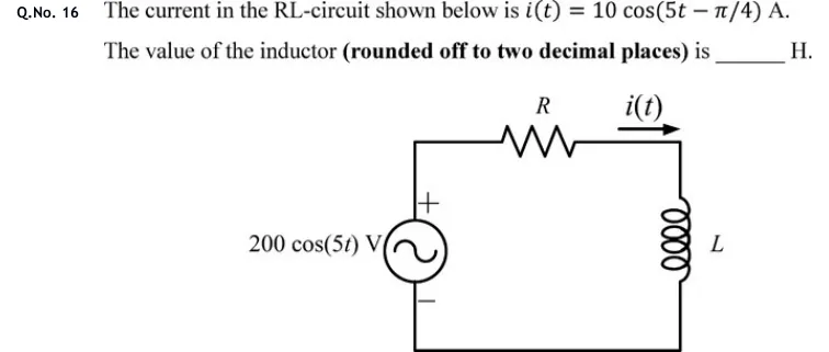
The current in the RL-circuit shown below is i(t)=10cos(5t−π/4)A. The value of the inductor (rounded off to two decimal places) is ______ H.
Tap to open full sizeFigure from the GATE 2020 EC paper. It is part of the question.Figure description
A single series loop. On the left branch is an independent sinusoidal voltage source labelled 200 cos (5t) V, with its + terminal at the top and - terminal at the bottom. From the source's top terminal a wire runs up and along the top branch through a resistor R (value not given) to the top-right corner; the current i(t) is marked on the top branch with an arrow pointing to the right, i.e. clockwise around the loop, leaving the source's + terminal. The right branch holds an inductor L running from the top-right corner down to the bottom-right corner. The bottom wire returns to the source's - terminal.
Tap to open full sizeFigure from the GATE 2020 EC paper. It is part of the question.Figure description
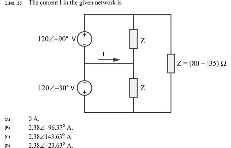
Three vertical branches connected between a top rail T and a bottom rail B. LEFT branch: two ideal AC voltage sources in series on the left vertical wire, with a mid-node M between them. The upper source is labelled 120∠−90° V, with + at the top (at T) and − at the bottom (at M). The lower source is labelled 120∠−30° V, with − at the top (at M) and + at the bottom (at B). MIDDLE branch: two impedances in series from T to B, each labelled Z. Their junction J is joined to M by a horizontal wire carrying current I, arrow pointing right (from M to J). RIGHT branch: one impedance from T to B labelled Z = (80 − j35) Ω, which gives the value of Z used for all three impedances.
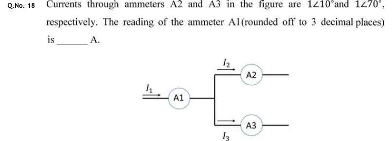
Currents through ammeters A2 and A3 in the figure are 1∠10∘ and 1∠70∘, respectively. The reading of the ammeter A1 (rounded off to 3 decimal places) is ______ A.
Tap to open full sizeFigure from the GATE 2020 EE paper. It is part of the question.Figure description
A single wire carries current I_1 (arrow pointing right) into ammeter A1. The wire leaving A1 goes to a junction node on a vertical conductor. The vertical conductor splits into two horizontal branches. The upper branch carries current I_2 (arrow pointing right) through ammeter A2 and continues to the right, open-ended. The lower branch carries current I_3 (arrow pointing right) through ammeter A3 and continues to the right, open-ended. No other elements are shown, so A1 measures the total current, which then divides between the A2 and A3 branches.
A cylindrical rotor synchronous generator with constant real power output and constant terminal voltage is supplying 100 A current to a 0.9 lagging power factor load. An ideal reactor is now connected in parallel with the load, as a result of which the total lagging reactive power requirement of the load is twice the previous value while the real power remains unchanged. The armature current is now ________ A (rounded off to 2 decimal places).
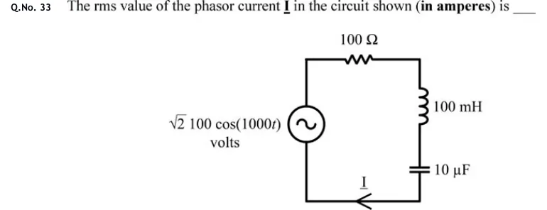
The rms value of the phasor current I in the circuit shown (in amperes) is ____
Tap to open full sizeFigure from the GATE 2020 IN paper. It is part of the question.Figure description
A single-loop series circuit. Left side: an AC voltage source (circle with a sine symbol, no polarity marks) labelled √ 2 100 cos (1000t) volts. The top wire runs from the source's top terminal through a 100 Ω resistor to the top-right corner. The right side, going down, has a 100 mH inductor and then a 10 capacitor in series. The bottom wire returns from the capacitor to the source's bottom terminal and carries the current I, marked with an arrow pointing left (from the capacitor side toward the source).
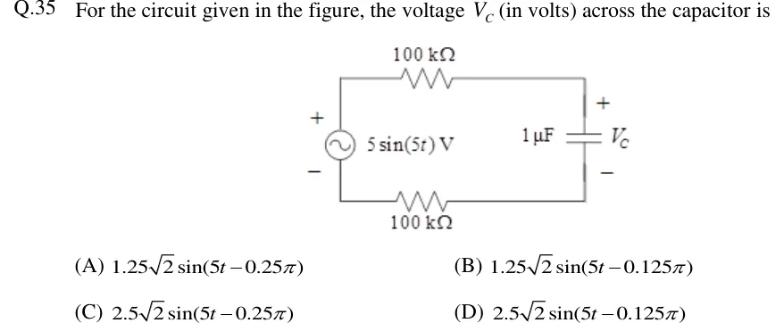
For the circuit given in the figure, the voltage VC (in volts) across the capacitor is
Tap to open full sizeFigure from the GATE 2018 EC paper. It is part of the question.Figure description
A single series loop. On the left is an AC voltage source 5 sin (5t) V, drawn with + at the top and − at the bottom. From the source's top terminal a wire runs through a 100 k Ω resistor along the top edge to the right-hand side. On the right-hand side is a 1 capacitor whose voltage V_C is marked + at its top plate and − at its bottom plate. From the capacitor's bottom plate a wire runs back through a second 100 k Ω resistor along the bottom edge to the source's bottom (−) terminal. So source, top resistor, capacitor and bottom resistor are all in series, and the source + and capacitor + are both on the top rail.
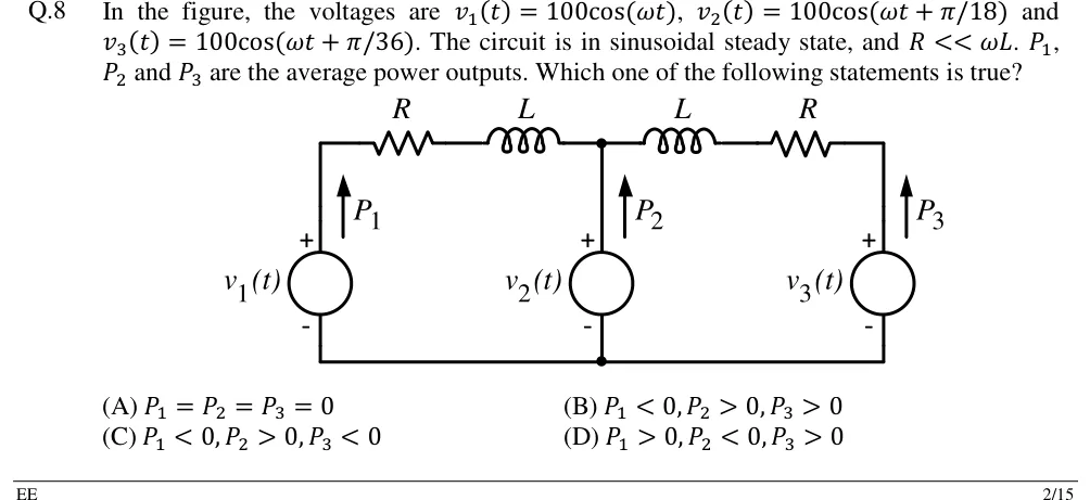
In the figure, the voltages are v1(t)=100cos(ωt),v2(t)=100cos(ωt+π/18) and v3(t)=100cos(ωt+π/36). The circuit is in sinusoidal steady state, and R<<ωL.P1,P2 and P3 are the average power outputs. Which one of the following statements is true?
Tap to open full sizeFigure from the GATE 2018 EE paper. It is part of the question.Figure description
Three ideal voltage sources share a common bottom (ground) wire. Left: source v_1(t), + terminal at top, with an upward arrow labelled P_1 beside it (power output). Middle: source v_2(t), + at top, upward arrow P_2. Right: source v_3(t), + at top, upward arrow P_3. Top rail: from the top of v_1 a series resistor R then an inductor L lead to the middle node, which is the top of v_2. From the middle node an inductor L then a resistor R lead to the top of v_3. So each outer source is connected to the middle source through an identical series branch R + j ω L; the bottom terminals of all three sources are joined.
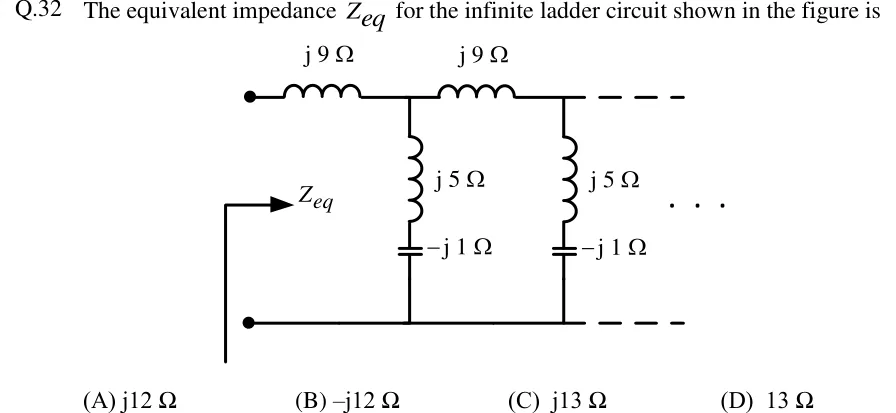
The equivalent impedance Zeq for the infinite ladder circuit shown in the figure is
Tap to open full sizeFigure from the GATE 2018 EE paper. It is part of the question.Figure description
An infinite ladder network between two input terminals (top-left and bottom-left dots). An arrow labelled Z_eq looks into the terminals. The top rail has repeated series elements, each an inductor marked j9 Ω. After each series element, a shunt branch runs from the top rail down to the bottom (return) rail. Each shunt branch is an inductor marked j5 Ω in series with a capacitor marked -j1 Ω. The pattern (series j9 Ω, then shunt j5 Ω + -j1 Ω) is drawn twice and continues indefinitely to the right, shown by dashed rails and dots. The bottom rail is a plain conductor.
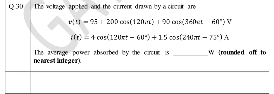
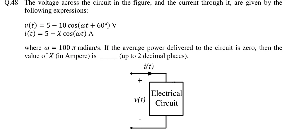
The voltage across the circuit in the figure, and the current through it, are given by the following expressions:
v(t)=5−10cos(ωt+60∘)V
i(t)=5+Xcos(ωt)A
where ω=100π radian/s. If the average power delivered to the circuit is zero, then the value of X (in Ampere) is ______ (up to 2 decimal places).
Tap to open full sizeFigure from the GATE 2018 EE paper. It is part of the question.Figure description
A two-terminal box labelled "Electrical Circuit". The top terminal wire carries a current i(t) with the arrow pointing into the box (left to right toward the box). The voltage v(t) is marked across the two terminals with + at the top terminal and - at the bottom terminal, so v and i follow the passive sign convention (power delivered to the circuit is v · i).
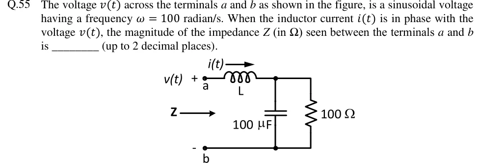
The voltage v(t) across the terminals a and b as shown in the figure, is a sinusoidal voltage having a frequency ω=100 radian/s. When the inductor current i(t) is in phase with the voltage v(t), the magnitude of the impedance Z (in Ω) seen between the terminals a and b is ________ (up to 2 decimal places).
Tap to open full sizeFigure from the GATE 2018 EE paper. It is part of the question.Figure description
Terminals a (top, marked +) and b (bottom, marked -), with v(t) applied across them and an arrow labelled Z pointing into the network from the a-b side. From terminal a, an inductor L is in series along the top wire, carrying current i(t) with its arrow pointing right (away from a). The right end of the inductor meets a top node. Between this top node and the bottom wire (which runs straight back to terminal b) there are two branches in parallel: a 100 µF capacitor and a 100 Ω resistor. So the circuit is L in series with (100 µF parallel with 100 Ω), seen from a-b.
A series R-C circuit is excited by a 1∠0V sinusoidal ac voltage source. The locus diagram of the phasor current I=(x+jy)A, when C is varied, while keeping R fixed, is
Tap to open full sizeFigure from the GATE 2018 IN paper. It is part of the question.Figure description
Each option is a sketch on complex-plane axes: horizontal axis labelled x (arrows both ways), vertical axis labelled +jy (arrows both ways). Each shows a semicircle with one end at the origin and the other end on the real axis. (A) semicircle above the positive x-axis (first quadrant), from the origin to a point on the positive x-axis. (B) semicircle below the positive x-axis (fourth quadrant), from the origin to a point on the positive x-axis. (C) semicircle above the negative x-axis (second quadrant), from a point on the negative x-axis to the origin. (D) semicircle below the negative x-axis (third quadrant), from a point on the negative x-axis to the origin.
(A)
Figure — semicircle in the first quadrant: starts at the origin, bulges upward (+jy), ends on the positive x-axis.
(B)
Figure — semicircle in the fourth quadrant: starts at the origin, bulges downward (−jy), ends on the positive x-axis.
(C)
Figure — semicircle in the second quadrant: from a point on the negative x-axis, bulges upward (+jy), ends at the origin.
(D)
Figure — semicircle in the third quadrant: from a point on the negative x-axis, bulges downward (−jy), ends at the origin.
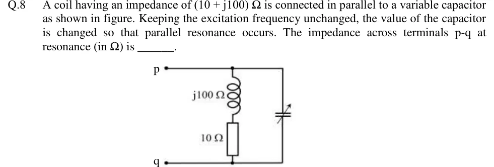
A coil having an impedance of (10+j100)Ω is connected in parallel to a variable capacitor as shown in figure. Keeping the excitation frequency unchanged, the value of the capacitor is changed so that parallel resonance occurs. The impedance across terminals p-q at resonance (in Ω) is ______.
Tap to open full sizeFigure from the GATE 2018 IN paper. It is part of the question.Figure description
Two open terminals, p at the top left and q at the bottom left. A horizontal wire from p runs right to a top rail; a horizontal wire from q runs right to a bottom rail. Between the rails are two parallel branches. Left branch (the coil): an inductor labelled j100 Ω at the top, in series with a resistor labelled 10 Ω below it, connected from the top rail to the bottom rail. Right branch: a variable capacitor (capacitor symbol with a diagonal arrow through it), connected from the top rail to the bottom rail. So terminals p-q see the series R-L coil (10 + j100) Ω in parallel with the variable capacitor.
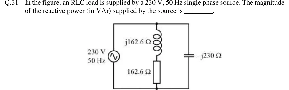
In the figure, an RLC load is supplied by a 230 V, 50 Hz single phase source. The magnitude of the reactive power (in VAr) supplied by the source is ________.
Tap to open full sizeFigure from the GATE 2018 IN paper. It is part of the question.Figure description
A 230 V, 50 Hz sinusoidal AC source sits on the left. Two branches are connected directly across it, in parallel: (1) a middle branch with an inductor of reactance j162.6 Ω (top) in series with a resistor of 162.6 Ω (bottom); (2) a right-hand branch with a capacitor of reactance −j230 Ω. There are only two nodes, the top rail and the bottom rail, so both branches see the full 230 V.
The rms value (in V) of v(t)=6+82sin(314t)+42cos(942t) V is ________ (round off to two decimal places).
▸ Answer and solution
Answer:10.77 (accepted range ±0.02)
The three components have different frequencies (0,314 and 942 rad/s), so their mean squares add.
Their rms values are 6 V, 82/2=8 V and 4 V.
Vrms=62+82+42=116=10.77 V.
PRACTICE 22 marks · MSQ
A load connected to a 250 V (rms) single-phase supply absorbs complex power S=3+j4 kVA, where S=VI∗ with rms phasors and the passive sign convention. Which of the following statements is/are correct?
(A)
The load power factor is 0.6 lagging.
(B)
The magnitude of the load current is 20 A.
(C)
The load impedance is 7.5−j10Ω.
(D)
A capacitor connected in parallel with the load and supplying 4 kvar reduces the supply current to 12 A.
▸ Answer and solution
Answer: (A), (B), (D)
∣S∣=32+42=5 kVA; pf =P/∣S∣=3/5=0.6.Q>0 means the load absorbs reactive power: inductive, lagging. (A) is correct.
∣I∣=∣S∣/∣V∣=5000/250=20 A. (B) is correct.
Z=∣V∣2/S∗=62500/(3000−j4000)=7.5+j10Ω, inductive as expected. (C) is wrong.
With the capacitor, the supply provides S=3+j0 kVA, so ∣I∣=3000/250=12 A. (D) is correct.
PRACTICE 32 marks · NAT
A source network has the Thevenin equivalent VTh=20∠0∘ V (rms) in series with ZTh=6+j8Ω at the operating frequency. A purely resistive load RL is connected and adjusted for maximum power transfer. The maximum power (in W) delivered to RL is ________ (round off to two decimal places).
▸ Answer and solution
Answer:12.5 (accepted range ±0.05)
For a purely resistive load, RL=∣ZTh∣=62+82=10Ω.
∣I∣=∣16+j8∣20=32020=1.118 A.
P=∣I∣2RL=320400×10=12.5 W. (A conjugate-matched load would receive 202/(4×6)=16.67 W; setting RL=6Ω gives only 400×6/(144+64)=11.54 W.)
PRACTICE 42 marks · MCQ
A coil of resistance 20Ω and inductance 0.2 H is connected in parallel with a 2μF capacitor. The angular frequency at which the combination draws a current in phase with the applied sinusoidal voltage, and the input impedance of the combination at that frequency, are respectively
(A)
1578 rad/s and 5000Ω
(B)
1581 rad/s and 5000Ω
(C)
1578 rad/s and 20Ω
(D)
1581 rad/s and 20Ω
▸ Answer and solution
Answer: (A)
Unity pf for a lossy coil in parallel with C: ω0=LC1−L2R2=0.4×10−61−0.04400=2.5×10⁶−104=2.49×106=1578 rad/s.
A series RLC circuit with R=20Ω,L=10 mH and C=1μF is driven by a sinusoidal voltage vin, and the output vout is taken across the capacitor with no load. For H(jω)=Vout/Vin, which of the following statements is/are correct?
(A)
The circuit is a low-pass filter.
(B)
∣H(jω)∣=5 at ω=104 rad/s.
(C)
∣H(jω)∣→1 as ω→∞.
(D)
At ω=104 rad/s the output lags the input by 90∘.
▸ Answer and solution
Answer: (A), (B), (D)
H(s)=s2+(R/L)s+1/(LC)1/(LC): ∣H(0)∣=1 and ∣H∣→0 as ω→∞, so it is a low-pass filter. (A) is correct and (C) is wrong.
ω0=1/LC=1/10−2×10−6=104 rad/s and Q=ω0L/R=(104×0.01)/20=5.
At s=jω0 the terms −ω02 and 1/(LC) cancel: H(jω0)=j104×2000108=j2×107108=−j5.
So ∣H(jω0)∣=5=Q, and the angle is −90∘: the output lags the input by 90∘. (B) and (D) are correct.
Sinusoidal steady state analysis: phasors, complex power, maximum power transfer
GATE EE
sinusoidal steady-state analysis, resonance … complex power and power factor in AC circuits
GATE IN
Peak, average and rms values of AC quantities; apparent, active and reactive powers, power factor; phasor analysis, impedance and admittance; series and parallel resonance, locus diagrams, realization of basic filters with R, L, and C elements

 Tap to open full size