
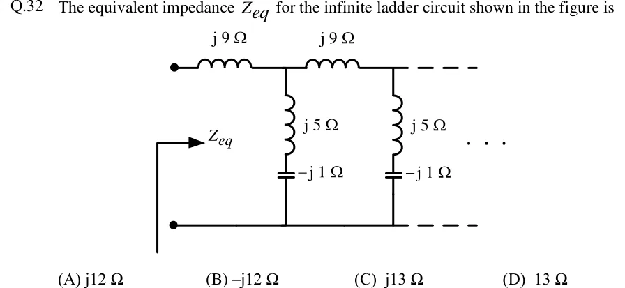
The equivalent impedance for the infinite ladder circuit shown in the figure is
 Tap to open full size
Figure description
An infinite ladder network between two input terminals (top-left and bottom-left dots). An arrow labelled Z_eq looks into the terminals. The top rail has repeated series elements, each an inductor marked j9 Ω. After each series element, a shunt branch runs from the top rail down to the bottom (return) rail. Each shunt branch is an inductor marked j5 Ω in series with a capacitor marked -j1 Ω. The pattern (series j9 Ω, then shunt j5 Ω + -j1 Ω) is drawn twice and continues indefinitely to the right, shown by dashed rails and dots. The bottom rail is a plain conductor.
- (A)
- (B)
- (C)
- (D)