
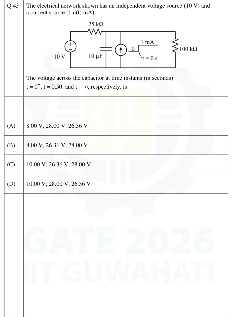
The electrical network shown has an independent voltage source (10 V) and a current source (1 u(t) mA).
[Figure]
The voltage across the capacitor at time instants (in seconds) , , and , respectively, is:
 Tap to open full size
Figure description
Single-node-pair circuit with a common bottom (reference) wire. Left branch: independent 10 V DC source, + terminal on top, - terminal on the bottom wire. From the + terminal, a 25 kΩ resistor runs along the top wire to the top node. Between the top node and the bottom wire, three elements are connected in parallel, left to right: (1) a 10 µF capacitor; (2) an independent current source with its arrow pointing up (it drives current from the bottom wire into the top node). Its waveform is drawn beside it as a step: 0 before t = 0 s, jumping to 1 mA at t = 0 s (i.e. 1 u(t) mA); (3) a 100 kΩ resistor on the far right.
- (A)
8.00 V, 28.00 V, 26.36 V
- (B)
8.00 V, 26.36 V, 28.00 V
- (C)
10.00 V, 26.36 V, 28.00 V
- (D)
10.00 V, 28.00 V, 26.36 V