
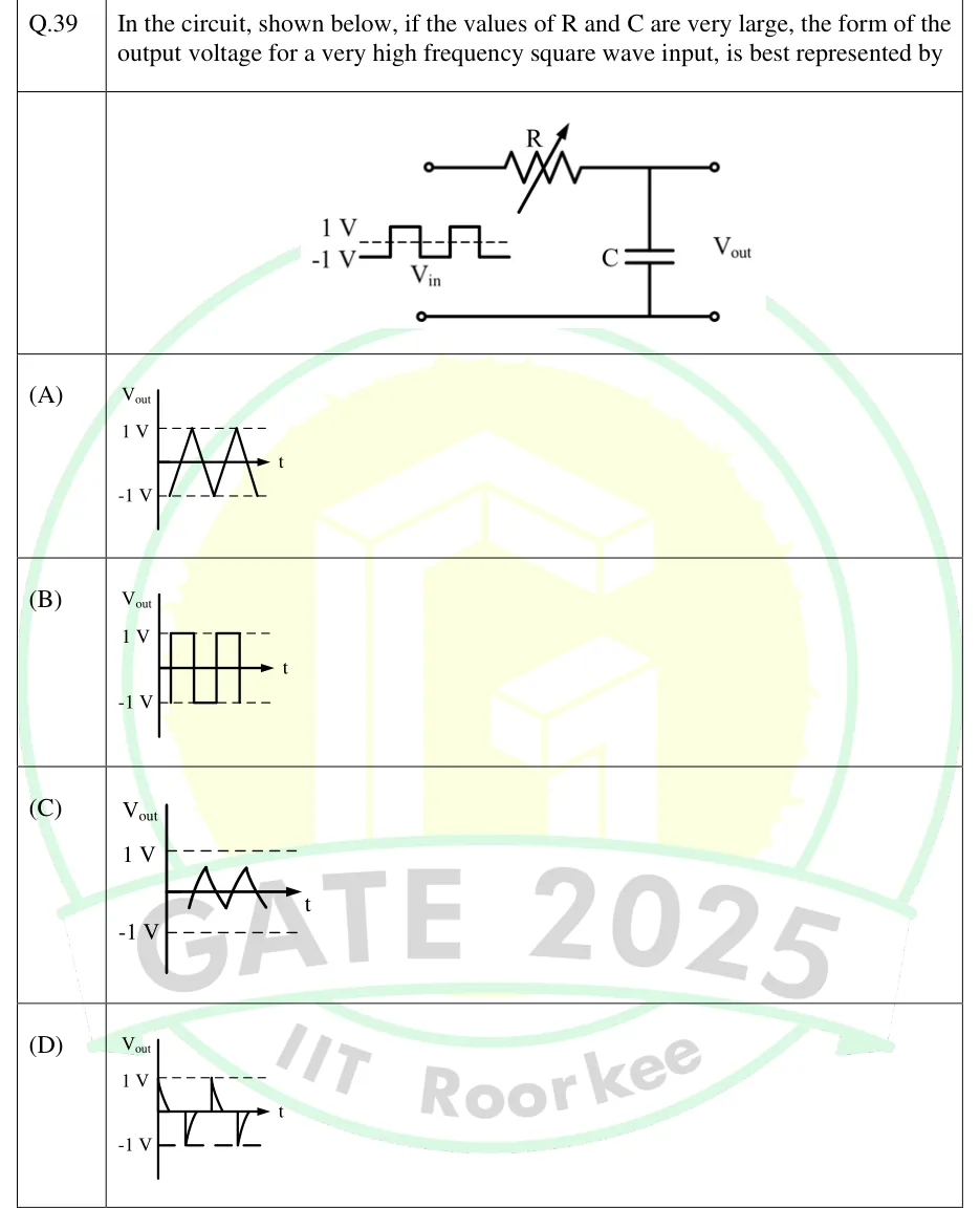
In the circuit, shown below, if the values of R and C are very large, the form of the output voltage for a very high frequency square wave input, is best represented by
 Tap to open full size
Figure description
Series RC low-pass network. From the top input terminal a variable resistor R (resistor symbol with a diagonal arrow through it) runs in series to a node. From that node a capacitor C goes down to the bottom (common) line, which runs straight from the bottom input terminal to the bottom output terminal. The output V_out is taken across the capacitor, between the top-right and bottom-right terminals. Next to the input terminals, the input V_in is sketched as a symmetric square wave that switches between +1 V and -1 V (labels '1 V' and '-1 V' at its high and low levels). It starts at -1 V on the left, and a single dashed line runs through the middle of the wave at the 0 V level.
- (A)
Figure: vs t is a triangular wave swinging the full range between and . Its peaks and troughs touch the dashed 1 V and -1 V lines.
- (B)
Figure: vs t is a square wave alternating between and (the same as the input).
- (C)
Figure: vs t is a small-amplitude triangular wave centred on the time axis (symmetric about 0 V). Its peaks sit only a fraction of a volt above and below the axis, far inside the dashed 1 V and -1 V lines.
- (D)
Figure: vs t is a train of exponential spikes. It starts at at t = 0 and decays to 0, stays at 0, jumps to at the next edge and decays back to 0, and so on alternately (a differentiated square wave).