
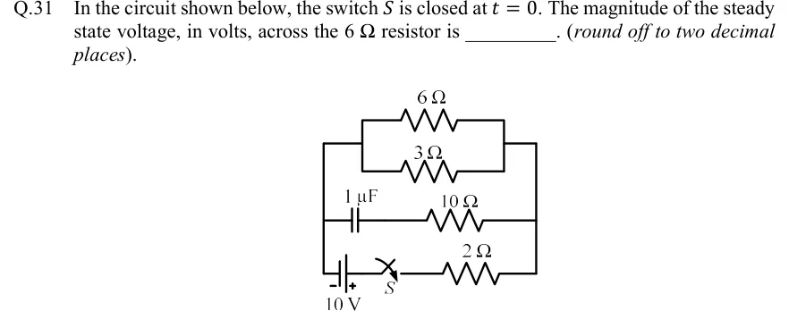
In the circuit shown below, the switch is closed at . The magnitude of the steady state voltage, in volts, across the resistor is ________. (round off to two decimal places).
 Tap to open full size
Figure description
Three branches are connected in parallel between a left vertical rail and a right vertical rail. Top branch: a 6 Ω resistor and a 3 Ω resistor in parallel with each other, the 6 Ω drawn above the 3 Ω. Their two ends join short vertical links, and horizontal wires tie those links to the outer left and right rails. Middle branch: a 1 capacitor in series with a 10 Ω resistor, capacitor on the left side and 10 Ω on the right, from the left rail to the right rail. Bottom branch: a 10 V battery at the bottom-left (negative terminal on the left, toward the left rail; positive terminal on the right), then switch S (open in the drawing, closed at t = 0), then a 2 Ω resistor running to the right rail.