
IAE Academy

GATE 2020 IN Q.7: solution and answer

GATE 2020 · INQ.7 · 1 mark · MCQ

If the diodes in the circuit shown are ideal and the breakdown voltage of the Zener diode is 5 V, the power dissipated in the resistor (in watts) is ____
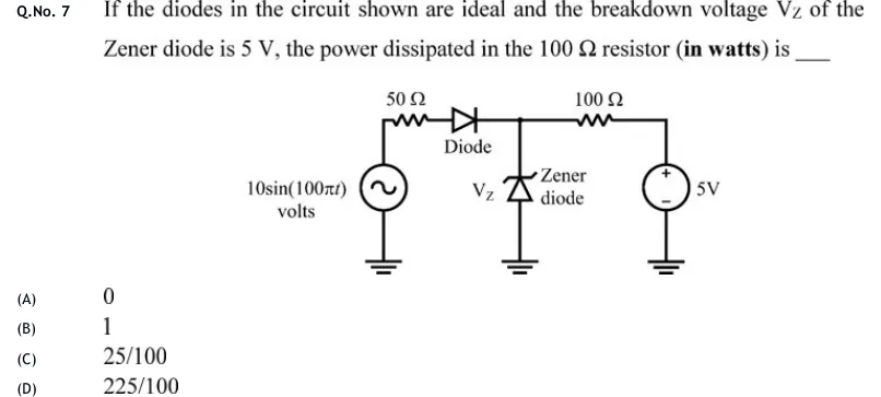
GATE 2020 IN question 7: An AC source 10 sin (100 π t) volts has its bottom terminal grounded.Tap to open full size
Figure from the GATE 2020 IN paper. It is part of the question.
Figure description

An AC source 10 sin (100 π t) volts has its bottom terminal grounded. From its top terminal a 50 Ω resistor runs to the right, then an ideal diode labelled "Diode" with its anode on the left (towards the resistor) and its cathode on the right, ending at a node. From this node a Zener diode labelled "Zener diode" (voltage marked V_Z) goes down to ground. The triangle points up and the bent bar is at the top, so the cathode is at the node and the anode is at ground. From the same node a 100 Ω resistor runs to the right to the + terminal of a 5 V DC source, whose - terminal is grounded.

  1. (A)

    0

  2. (B)

    1

  3. (C)

    25/100

  4. (D)

    225/100

Answer and solution

ANSWER

The power dissipated in the 100 Ω resistor is 0 W (option A). The node is held at 5 V at every instant: by the battery when the diode is off, and by the Zener in breakdown when it is on. So both ends of the 100 Ω resistor are at the same voltage.

Official answer: ASource: Official answer key, GATE 2020 IN (IIT Delhi)

  1. Read the orientations. Call the junction of the diode, the Zener and the resistor the node, at voltage . The series diode has its anode towards the resistor, so it conducts only when is above . The Zener has its cathode at the node and its anode at ground. Taking it as ideal: it carries no current for , it breaks down and holds when reverse current is forced into it, and it would conduct forward only if .

  2. Diode off (). The diode cuts the source off from the node. Only the 5 V battery and the resistor drive the node. The Zener cannot conduct below , so there is no path for current, and . That is exactly the breakdown voltage, with zero Zener current, so the assumption is consistent.

  3. Diode on (). Suppose the Zener stayed off. KCL at the node would give . The left side is positive because the diode conducts, so . The Zener cannot block more than , so this is a contradiction. The Zener is therefore in breakdown and holds . All of the source current flows down through the Zener.

  4. Negative half-cycle, or . The diode's anode is below its cathode at , so the diode is reverse-biased and step 2 applies: . Forward-biasing the Zener would need . With the diode off, nothing can pull the node below the battery's .

  5. So at every instant. Both ends of the resistor are at . By Ohm's law,

  6. Power: at every instant, so the average power is also . Answer: (A).

KEY IDEA

The Zener's breakdown voltage (5 V) equals the battery voltage (5 V). When the series diode is off, the battery sets the node at 5 V through the 100 Ω resistor with no current flowing. When the diode is on, the ideal Zener breaks down and clamps the node at 5 V, taking all the source current. Either way the voltage across the 100 Ω resistor is zero, so it carries no current.

WATCH OUT FOR

Ignoring the Zener clamp and putting the source peak minus the battery, , across the resistor gives (option C). Reading the battery polarity backwards, , gives (option D). The Zener pins the node at exactly the battery voltage, so the resistor never sees any voltage across it.

From the GATE 2020 IN paper. Every question of this paper · Download the full paper · All 25 Diode circuits questions, with notes

More Diode circuits questions