
IAE Academy

GATE 2022 EE Q.36: solution and answer

GATE 2022 · EEQ.36 · 2 marks · MCQ

The output impedance of a non-ideal operational amplifier is denoted by . The variation in the magnitude of with increasing frequency, , in the circuit shown below, is best represented by
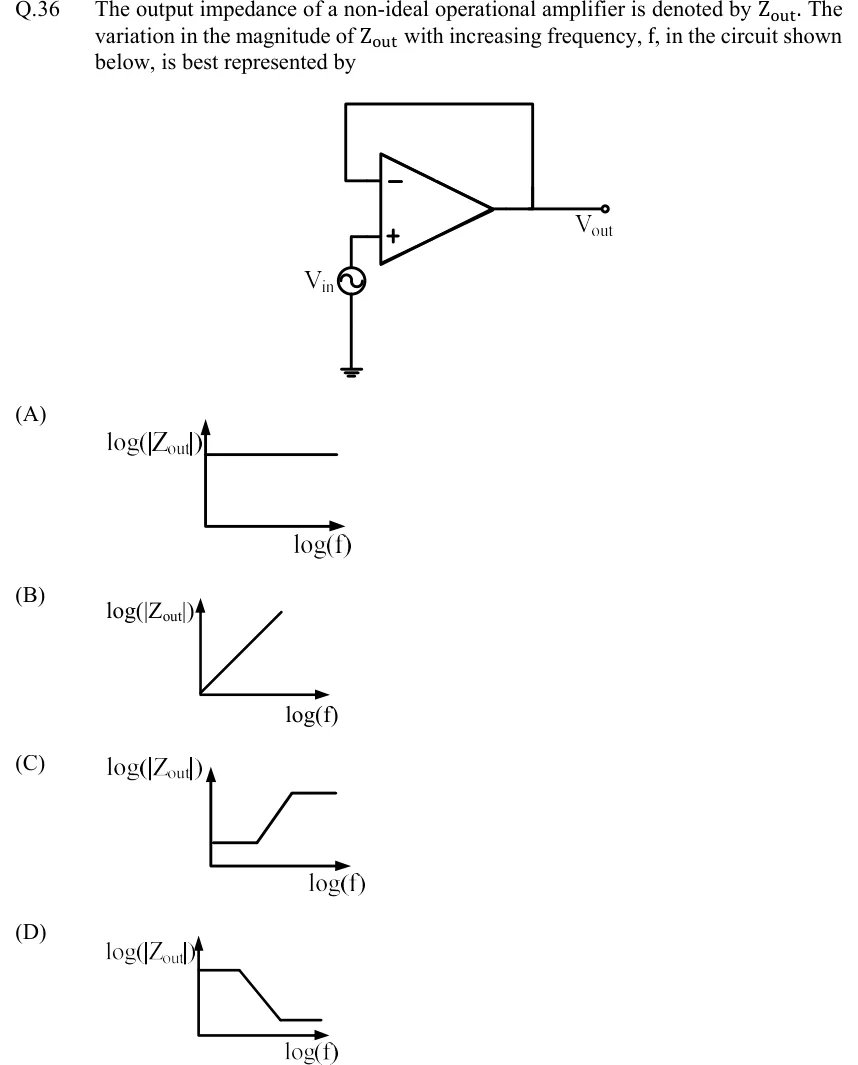
GATE 2022 EE question 36: Op-amp voltage follower (unity-gain buffer).Tap to open full size
Figure from the GATE 2022 EE paper. It is part of the question.
Figure description

Op-amp voltage follower (unity-gain buffer). The op-amp output is connected directly by a wire back to its inverting (−) input; there are no resistors. The non-inverting (+) input is driven by an AC source V_in whose other terminal is grounded. The output node is labelled V_out. Options are four plots of log (|Z_out|) (vertical axis) against log (f) (horizontal axis).

  1. (A)

    Figure — vs : a horizontal line, constant at all frequencies.

  2. (B)

    Figure — vs : a straight line rising from the origin, increasing at all frequencies.

  3. (C)

    Figure — vs : flat at a low level, then a rising straight segment, then flat again at a higher level.

  4. (D)

    Figure — vs : flat at a high level, then a falling straight segment, then flat again at a lower level.

Answer and solution

ANSWER

(C): is flat at at low frequencies, rises at between and , and levels off at above .

Official answer: CSource: Official answer key, GATE 2022 EE (IIT Kharagpur)

  1. Model. The circuit is a voltage follower: the output is wired straight back to the inverting input, so the feedback factor is . Model the non-ideal op-amp as an infinite input impedance, an open-loop output resistance and a single-pole open-loop gain , where is the open-loop break frequency.

  2. Output impedance by a test source. Set , so the non-inverting input is grounded, and apply a test voltage at the output. The inverting input sits at , so the op-amp's internal source is . The current into the output terminal is . Therefore This is the standard result for voltage-sampling (shunt-output) negative feedback: the open-loop output resistance is divided by .

  3. Substitute :

  4. Read off the zero and the pole. The zero is at . The pole is at , the unity-gain frequency. Since , the pole lies far above the zero.

  5. Low frequencies, : . This is very small and does not depend on , so the plot is flat at a low level.

  6. Mid band, : the numerator is about and the denominator is about , so . It is proportional to and rises at , a straight rising segment on the log-log axes. In this band the output behaves like an inductor, because the loop gain that was holding down is falling at .

  7. High frequencies, : both terms dominate, so . The loop gain is gone and the plot is flat again, at the higher level .

  8. Shape: low and flat, then rising, then high and flat. Option (A) is the ideal-feedback picture with no frequency dependence, (B) never levels off, and (D) is the reverse trend. The answer is (C).

KEY IDEA

Voltage-sampling negative feedback divides the op-amp's open-loop output resistance by . For a follower , so . The open-loop gain rolls off above , so rises from to between and : a zero at and a pole at about .

WATCH OUT FOR

Treating the op-amp as ideal, so that at every frequency, and picking the flat plot (A). The question says the op-amp is non-ideal. Another mistake is sketching the shape of the open-loop gain curve (flat, falling, flat) and picking (D). varies inversely with the loop gain, so it rises where the gain falls.

From the GATE 2022 EE paper. Every question of this paper · Download the full paper · All 36 Op-amps questions, with notes

More Op-amps questions