
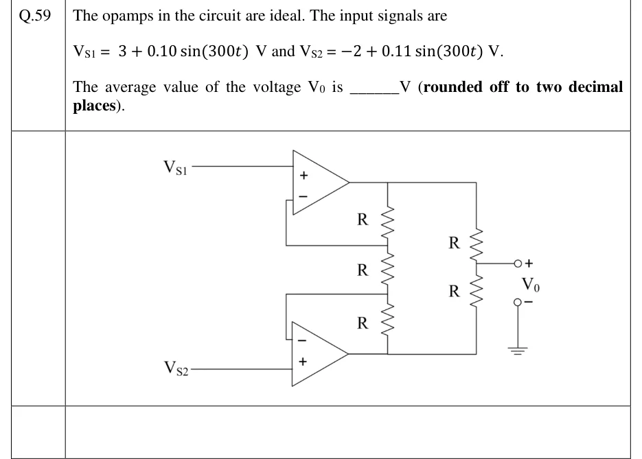
The opamps in the circuit are ideal. The input signals are
and .
The average value of the voltage is ______ V (rounded off to two decimal places).
 Tap to open full size
Figure description
Two ideal op-amps, one above the other. Top op-amp: non-inverting (+) input is driven by V_S1; its inverting (−) input is wired to node A. Bottom op-amp: non-inverting (+) input is driven by V_S2; its inverting (−) input is wired to node B. Left resistor chain, three equal resistors R in series from the top op-amp's output down to the bottom op-amp's output: top op-amp output — R — node A — R — node B — R — bottom op-amp output. So each op-amp's feedback resistor is an outer R, and the middle R sits between the two inverting inputs. Right resistor chain: two equal resistors R in series from the top op-amp's output to the bottom op-amp's output. Their junction is the output terminal V_O (+). The V_O (−) terminal is ground. This is the input stage of the three-op-amp instrumentation amplifier, with its output taken at the midpoint of a two-resistor divider.