
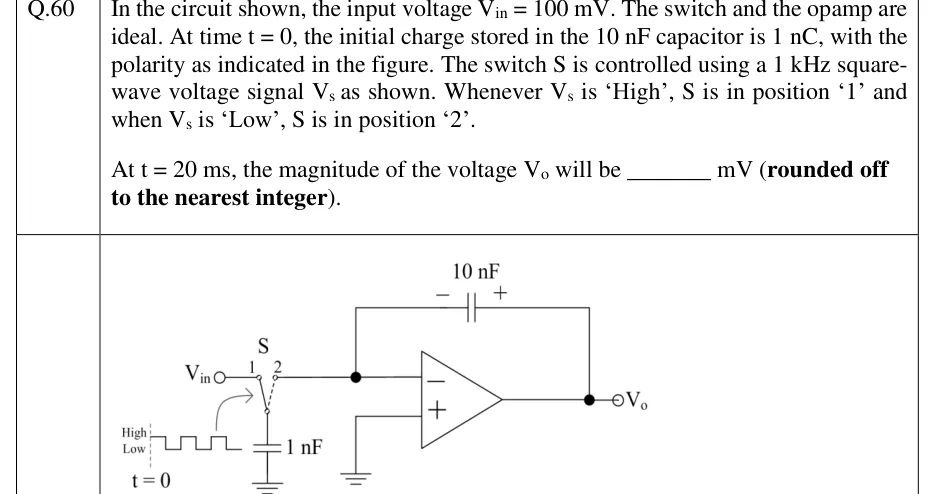
In the circuit shown, the input voltage . The switch and the opamp are ideal. At time , the initial charge stored in the capacitor is , with the polarity as indicated in the figure. The switch S is controlled using a square-wave voltage signal as shown. Whenever is 'High', S is in position '1' and when is 'Low', S is in position '2'.
At , the magnitude of the voltage will be ________ mV (rounded off to the nearest integer).
 Tap to open full size
Figure description
Switched-capacitor integrator. A single-pole double-throw switch S has its common (moving) terminal connected to the top plate of a 1 nF capacitor whose bottom plate is grounded. Throw '1' of S connects to the input terminal V_in; throw '2' connects to the inverting (−) input of an op-amp. A 10 nF capacitor is connected from the inverting input to the op-amp output V_o, with its polarity marked '−' on the inverting-input side (left plate) and '+' on the output side (right plate). The non-inverting (+) input of the op-amp is grounded. No other components. A curved arrow from the control waveform to the switch indicates V_s drives S. Control waveform V_s: a square wave between levels 'Low' and 'High', starting at t = 0 (dashed vertical line) in the High state, then Low, High, Low, High, Low (equal half-periods); frequency 1 kHz.