
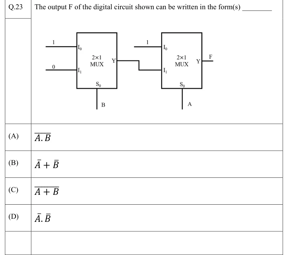
The output F of the digital circuit shown can be written in the form(s) ________
 Tap to open full size
Figure description
Two 2×1 multiplexers connected in cascade. First (left) MUX: input I_0 = 1, input I_1 = 0, select line S_0 = B; its output Y goes to the I_1 input of the second MUX. Second (right) MUX: input I_0 = 1, input I_1 = output Y of the first MUX, select line S_0 = A; its output Y is F.
- (A)
- (B)
- (C)
- (D)