
IAE Academy

GATE 2022 EC Q.18: solution and answer

GATE 2022 · ECQ.18 · 1 mark · MCQ

Consider the CMOS circuit shown in the figure (substrates are connected to their respective sources). The gate width () to gate length () ratios of the transistors are as shown. Both the transistors have the same gate oxide capacitance per unit area. For the MOSFET, the threshold voltage is and the mobility of holes is . For the MOSFET, the threshold voltage is and the mobility of electrons is . The steady state output voltage is ________.
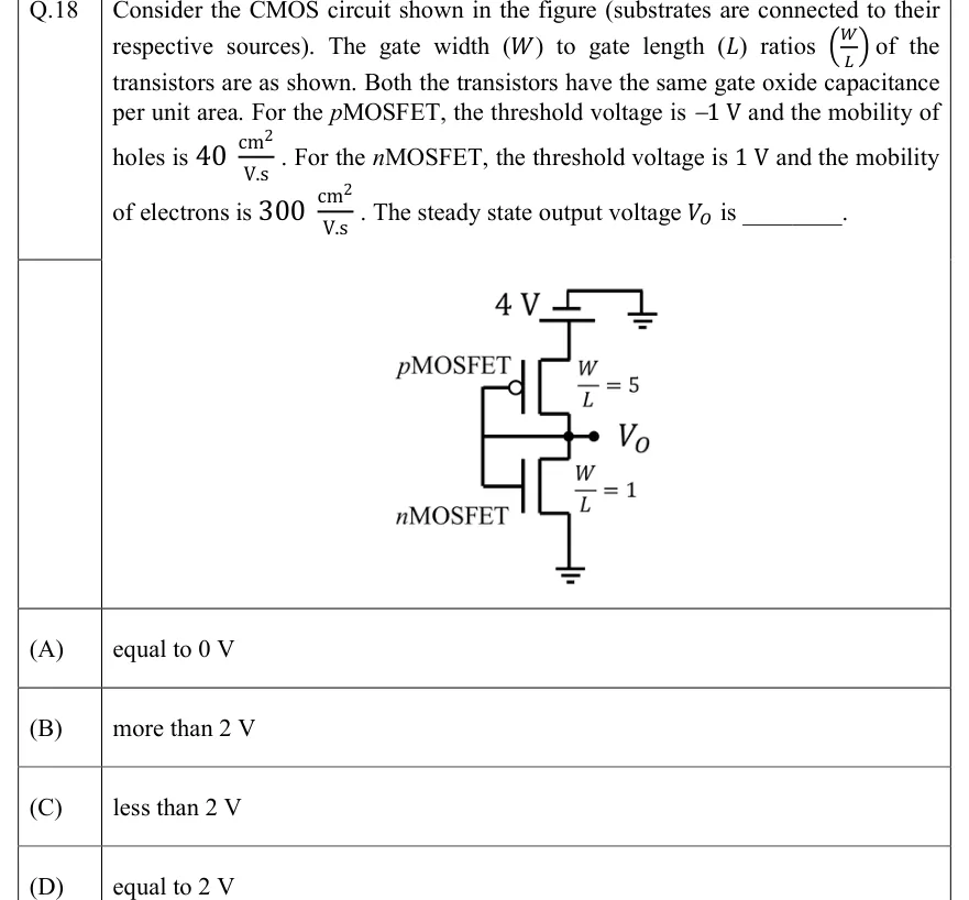
GATE 2022 EC question 18: A CMOS inverter-style stack between a 4 V supply (top) and ground (bottom).Tap to open full size
Figure from the GATE 2022 EC paper. It is part of the question.
Figure description

A CMOS inverter-style stack between a 4 V supply (top) and ground (bottom). The top device is a pMOSFET (labelled pMOSFET, with the gate bubble) with W/L = 5; its source is connected to the 4 V rail. The bottom device is an nMOSFET (labelled nMOSFET) with W/L = 1; its source is connected to ground. The two drains are joined at a node that is brought out as the output V_O. The gates of the two transistors are tied together by a vertical line on the left, and this gate line is connected by a horizontal wire directly to the common drain node V_O, so the input is shorted to the output (both transistors are diode-connected). There is no separate input terminal. Substrates are tied to their respective sources.

  1. (A)

    equal to 0 V

  2. (B)

    more than 2 V

  3. (C)

    less than 2 V

  4. (D)

    equal to 2 V

Answer and solution

ANSWER

(C) less than 2 V. Both diode-connected transistors are in saturation, and equating their currents gives .

Official answer: CSource: Official answer key, GATE 2022 EC (IIT Kharagpur)

  1. Read the figure. The two gates are tied together and wired to the common drain node, so and . For each device the drain sits at its own gate: and . Whenever a device conducts, , so both transistors are in saturation (each is diode-connected). Each substrate is tied to its source, so there is no body effect and the thresholds stay at and .

  2. Both devices must be on. If the nMOS is off while the pMOS conducts and charges the node upward, so cannot stay there. If the pMOS is off while the nMOS discharges the node. So in steady state .

  3. Saturation (square-law) current, ignoring channel-length modulation: , where is the overdrive voltage (for the pMOS, ).

  4. Strength factors (the common cancels, since both devices have the same oxide capacitance per unit area): and .

  5. In steady state the same current flows through both devices (nothing is connected to the output):

  6. Take the positive square root, since both overdrives are positive in the range : , with .

  7. Check: and , so both devices are on and in saturation, as assumed. , which is less than .

  8. Quick sanity check: the thresholds are symmetric (), so would be exactly only if . Here (300 against 200), so the stronger nMOS pulls the node below 2 V. Answer (C).

KEY IDEA

With gate tied to drain, a MOSFET that conducts is always in saturation. Here both are, so equate the square-law currents . With symmetric thresholds, the node sits at only when . Otherwise the stronger device pulls it towards its own rail. Here , so the nMOS wins and .

WATCH OUT FOR

Seeing against and concluding the pMOS is stronger, which gives (B). Device strength is , not alone. The electron mobility is 7.5 times the hole mobility, so . Choosing (D) also comes from ignoring the mobilities, or from assuming a CMOS stack always settles at . Some students treat the circuit as an inverter with an unknown input and pick (A). The figure shorts gate to drain, so there is no free input.

From the GATE 2022 EC paper. Every question of this paper · Download the full paper · All 7 Logic families questions, with notes

More Logic families questions