
IAE Academy

GATE 2026 EC Q.20: solution and answer

GATE 2026 · ECQ.20 · 1 mark · MCQ

In the circuit shown in the Figure, and are logic inputs and is the logic output.

Which of the following logic operations is realized by the circuit?
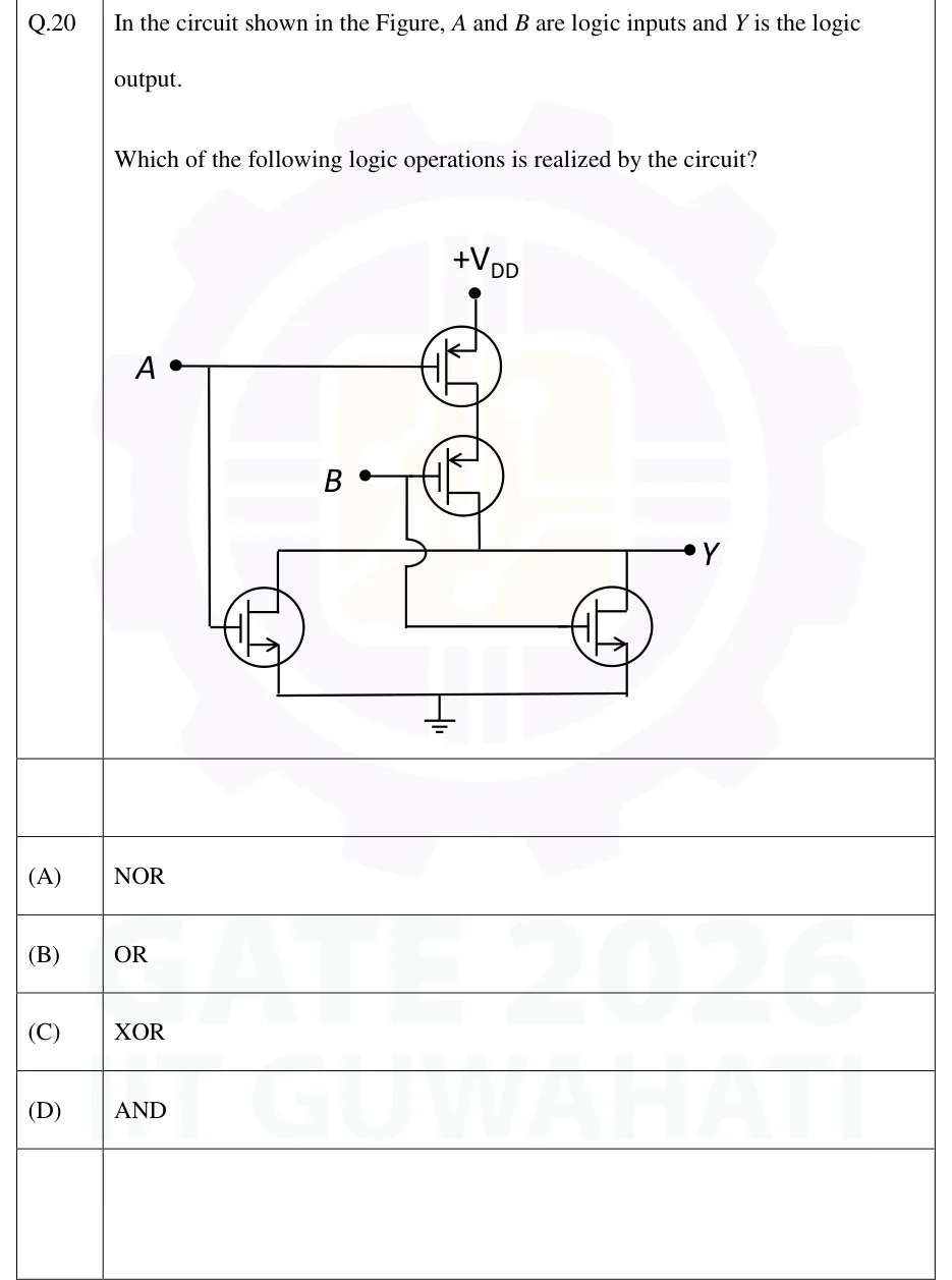
GATE 2026 EC question 20: A four-transistor CMOS gate.Tap to open full size
Figure from the GATE 2026 EC paper. It is part of the question.
Figure description

A four-transistor CMOS gate. Pull-up network: two enhancement PMOS transistors in series between +V_DD and the output node Y. The upper PMOS has its source at +V_DD and its gate driven by input A. The lower PMOS has its source on the upper PMOS's drain, its gate driven by input B, and its drain on the output line Y. Pull-down network: two enhancement NMOS transistors in parallel between Y and ground. The left NMOS has its gate on input A (a wire drops from the A input line), its drain on the Y line and its source on the common ground rail. The right NMOS has its gate on input B (a wire drops from the B input and crosses the Y line with a hop, so it is not connected to it), its drain on the Y line and its source on the common ground rail. The output Y is taken from the node where the lower PMOS drain meets both NMOS drains. The PMOS source arrows point into the channel and the NMOS source arrows point out of it.

  1. (A)

    NOR

  2. (B)

    OR

  3. (C)

    XOR

  4. (D)

    AND

Answer and solution

ANSWER

The circuit realizes (overline means complement), which is the 2-input NOR gate. Option (A).

Official answer: ASource: Official answer key, GATE 2026 EC (IIT Guwahati)

  1. Identify the devices from the source arrows. The two upper transistors have the arrow on the source pointing into the channel, and the top one's source is at . They are enhancement PMOS devices and form the pull-up network. The two lower transistors have the arrow pointing out of the channel, with their sources on the ground rail. They are enhancement NMOS devices and form the pull-down network.

  2. Read the topology. The PMOS gated by and the PMOS gated by are in series between and : the drain of the upper one feeds the source of the lower one. The NMOS gated by and the NMOS gated by are in parallel between and ground, with both drains on the line and both sources on the ground rail. The wire from hops over the line, so it does not connect to . It only drives the gate of the right NMOS.

  3. Switching rules: an NMOS conducts when its gate is at logic 1, and a PMOS conducts when its gate is at logic 0.

  4. Pull-down network: the parallel NMOS pair connects to ground when or . So exactly when .

  5. Pull-up check: the series PMOS pair connects to only when and , which is . By De Morgan, , the exact complement of the pull-down condition. So for every input exactly one network conducts, as a static CMOS gate requires.

  6. Truth table: . For , .

  7. So (overline means complement). This is the 2-input NOR gate, option (A).

KEY IDEA

In a static CMOS gate, the NMOS pull-down network directly implements the complement of the output. Parallel NMOS devices give OR, and series NMOS devices give AND. The PMOS pull-up network is the dual: series where the NMOS are parallel, and parallel where they are in series. Parallel NMOS with series PMOS gives , which is NOR.

WATCH OUT FOR

Reading the output from the pull-down function without inverting it. The parallel NMOS pair computes , but it pulls LOW, so the answer is NOR, not OR. A second slip is mixing up the dual pair: series PMOS with parallel NMOS gives NOR, while parallel PMOS with series NMOS gives NAND. It also helps to notice the hop on the wire, which shows does not connect to the output line.

From the GATE 2026 EC paper. Every question of this paper · Download the full paper · All 7 Logic families questions, with notes

More Logic families questions