
The following circuit(s) representing a lumped element equivalent of an infinitesimal section of a transmission line is/are
 Tap to open full size
Figure description
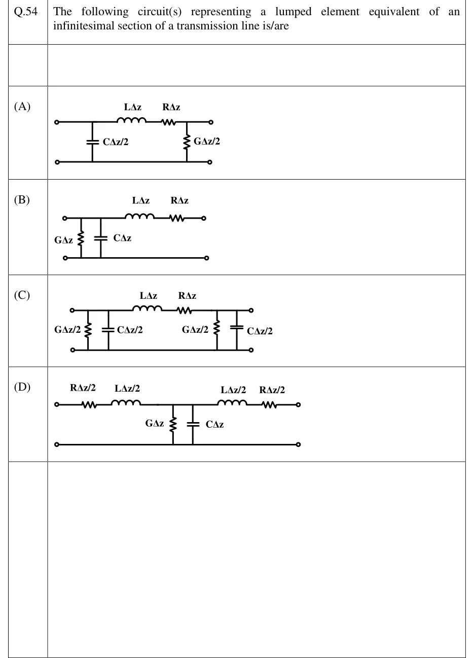
Each option is a two-port with a top (signal) wire and a bottom (return) wire, input terminals on the left and output terminals on the right. (A) Top wire: series inductor L Δ z followed by series resistor R Δ z. Shunt branches: a capacitor C Δ z/2 across the input side (before the inductor) and a resistor (conductance) G Δ z/2 across the output side (after the resistor). There is no shunt G at the input and no shunt C at the output. (B) Shunt conductance G Δ z and shunt capacitor C Δ z in parallel across the input terminals, then series inductor L Δ z and series resistor R Δ z on the top wire to the output (L-section). (C) Shunt G Δ z/2 and C Δ z/2 in parallel across the input, series L Δ z and R Δ z on the top wire, then shunt G Δ z/2 and C Δ z/2 in parallel across the output (pi-section). (D) Top wire: series R Δ z/2, series L Δ z/2, then at the midpoint a shunt G Δ z in parallel with C Δ z to the bottom wire, then series L Δ z/2 and series R Δ z/2 to the output (T-section).
- (A)
Figure — series and ; shunt only at the input side and shunt only at the output side
- (B)
Figure — shunt at the input, followed by series and
- (C)
Figure — shunt at the input, series and , shunt at the output
- (D)
Figure — series and , shunt at the middle, series and