
IAE Academy

GATE 2023 IN Q.34: solution and answer

GATE 2023 · INQ.34 · 1 mark · NAT

The full-scale range of the wattmeter shown in the circuit is 100 W. The turns ratio of the individual transformers are indicated in the figure. The RMS value of the ac source voltage V_s is 200 V. The wattmeter reading will be ________ W (rounded off to the nearest integer).
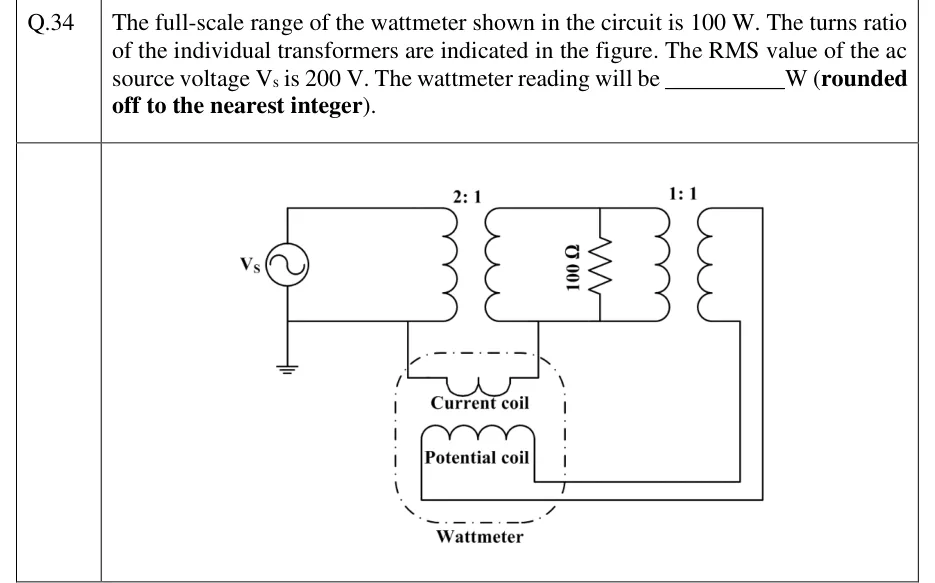
GATE 2023 IN question 34: An ac source V_s has its lower terminal grounded.Tap to open full size
Figure from the GATE 2023 IN paper. It is part of the question.
Figure description

An ac source V_s has its lower terminal grounded. The source is connected directly across the primary of transformer T1, turns ratio 2:1: its upper terminal goes to the top of the primary and its lower (grounded) terminal to the bottom. The secondary of T1 feeds a 100 Ω resistor and, in parallel with it, the primary of a second transformer T2 with turns ratio 1:1. The top and bottom rails of the secondary loop join the secondary, the resistor and T2's primary. A wattmeter, drawn as a dash-dot box, holds a current coil and a potential coil. The current coil's left end connects to the grounded lower wire of the source/T1-primary loop, and its right end connects to the lower wire of the T1-secondary loop. No other conductor joins the primary side to the secondary side. The potential coil sits across T2's secondary: one end goes to T2's lower secondary terminal and the other runs round to T2's upper secondary terminal. T2's secondary connects to nothing else.

Answer and solution

ANSWER

The wattmeter reads 0 W. Its current coil only joins two galvanically isolated circuits, so no current flows through it, even though the potential coil sees 100 V.

Official answer: 0Source: Official answer key, GATE 2023 IN (IIT Kanpur)

  1. Potential coil: the T1 secondary voltage is . This voltage sits across both the resistor and T2's primary. T2 is , so the potential coil, which is connected across T2's secondary, sees .

  2. Current coil: one end is on the grounded return wire of the source/T1-primary loop and the other end is on the lower wire of the T1-secondary loop. So the coil is not in series with any loop that carries load current.

  3. An ideal transformer couples its windings only magnetically, so the primary loop and the secondary loop share no conductor. The current coil is the only wire that joins the two circuits.

  4. Apply KCL to the isolated secondary network. Any current that enters it through one conductor has to leave through another, and there is no second conductor. Therefore . All the coil does is fix the secondary circuit's potential relative to ground.

  5. Wattmeter deflection is proportional to , so the meter reads .

  6. For contrast, the resistor really does dissipate , which equals the meter's full scale. The current coil never carries that current, though, so the meter does not register it.

KEY IDEA

A wattmeter shows a reading only when current flows through its current coil. Here the current coil is the only conductor between the primary circuit and the secondary circuit, which the transformer isolates from each other. KCL gives no return path, so and the reading is whatever the potential-coil voltage.

WATCH OUT FOR

Working out the resistor's power, , and answering 100 W, the meter's full scale. That assumes the current coil carries the secondary load current, but it does not: it only bridges the grounded primary return to the secondary loop and forms no closed path.

From the GATE 2023 IN paper. Every question of this paper · Download the full paper · All 8 V, I, power & energy questions, with notes

More V, I, power & energy questions