
IAE Academy

GATE 2025 EE Q.58: solution and answer

GATE 2025 · EEQ.58 · 2 marks · NAT

In an experiment to measure the active power drawn by a single-phase RL Load connected to an AC source through a resistor, three voltmeters are connected as shown in the figure below. The voltmeter readings are as follows: , , . Assuming perfect resistors and ideal voltmeters, the Load-active power measured in this experiment, in W, is ________ (round off to one decimal place).
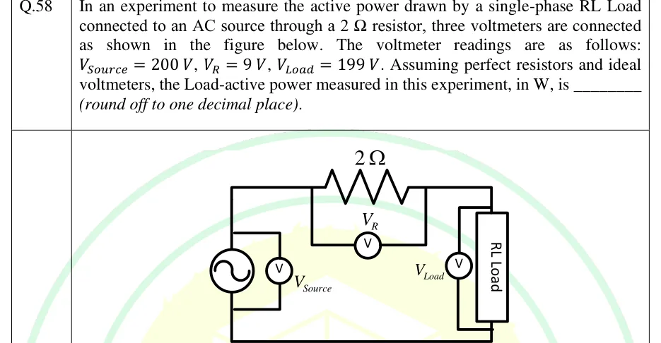
GATE 2025 EE question 58: Single series loop.Tap to open full size
Figure from the GATE 2025 EE paper. It is part of the question.
Figure description

Single series loop. On the left is an AC voltage source (sine symbol in a circle) with a voltmeter labelled V_Source connected directly across its terminals. The top wire from the source passes through a 2 Ω resistor; a voltmeter labelled V_R is connected across the resistor only (its leads tap the wire on either side of the resistor). The top wire then goes to the right-hand element, a box labelled 'RL Load', with a voltmeter labelled V_Load connected directly across the load terminals. The bottom wire returns from the load to the source. So the source, the 2 Ω resistor and the RL load are in series; the three voltmeters read the source voltage, the resistor voltage and the load voltage respectively.

Answer and solution

ANSWER

The load active power measured by the three-voltmeter method is .

Official answer: 78.0 to 81.0Source: Official answer key, GATE 2025 EE (IIT Roorkee)

  1. This is the three-voltmeter method. A known series resistor carries the load current , and the three voltmeters read the supply voltage , the resistor voltage and the load voltage .

  2. Take the current as the reference phasor. The resistor voltage is in phase with , and the RL load voltage leads by the load power-factor angle . The supply voltage is the phasor sum , and the angle between and is , so by the cosine rule:

  3. The load active power is with (ideal voltmeters draw no current, so the same flows in and the load). Substituting:

  4. Substitute the readings: , , , so .

  5. Check: and , so . The power factor is about lagging, a highly inductive load, which is consistent with an RL load.

KEY IDEA

Three-voltmeter method: the series resistor voltage is in phase with the current, so the supply voltage is the phasor sum of and with angle between them. The cosine rule gives , and with the load power reduces to . Only the three readings and are needed.

WATCH OUT FOR

Adding the voltages arithmetically () and concluding the data are inconsistent, when they are phasors at an angle. Other mistakes: dividing by or by instead of (giving or ), including the resistor's own loss in the load power, or using a minus sign in the cosine rule, which gives a negative .

From the GATE 2025 EE paper. Every question of this paper · Download the full paper · All 8 V, I, power & energy questions, with notes

More V, I, power & energy questions