
IAE Academy

GATE 2025 IN Q.21: solution and answer

GATE 2025 · INQ.21 · 1 mark · MCQ

In a single-phase AC circuit, the power consumed by load resistance for an excitation is measured using a wattmeter. The same wattmeter is connected in two different topologies, Topology-A and Topology-B, as shown in the figure. Different branch currents and voltage drops are also marked in the figure. Among the following options, the condition that ensures low error in the wattmeter reading for both the topologies is
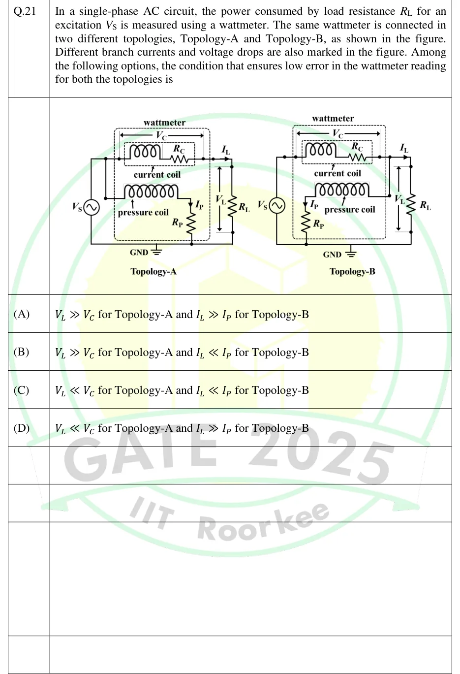
GATE 2025 IN question 21: Two circuits side by side, each with an AC source V_S on the left whose lower terminal goes to a common bottom rail marked…Tap to open full size
Figure from the GATE 2025 IN paper. It is part of the question.
Figure description

Two circuits side by side, each with an AC source V_S on the left whose lower terminal goes to a common bottom rail marked GND, and a load resistor R_L on the right between the top wire and the bottom rail. A dashed box labelled 'wattmeter' holds a current coil (inductor symbol in series with resistance R_C, in an inner dashed box labelled 'current coil') in the top wire, with the voltage across it marked V_C by a double-headed arrow spanning the coil. Below it is the pressure coil (inductor symbol) in series with resistance R_P, carrying current I_P (arrow pointing down through R_P), and the lower end of R_P goes to the bottom rail/GND. The load current I_L is marked by an arrow in the top wire just before R_L, and the voltage across R_L is marked V_L by a vertical double-headed arrow. Topology-A: the pressure-coil branch is tapped from the top wire on the SOURCE side of the current coil (left of the current coil). So the current coil carries only I_L, and the pressure coil plus R_P is across V_S = V_C + V_L. Topology-B: the pressure-coil branch is tapped from the top wire on the LOAD side of the current coil (right of the current coil, before the I_L arrow). So the pressure coil plus R_P is across V_L only, and the current coil carries I_L + I_P.

  1. (A)

    for Topology-A and for Topology-B

  2. (B)

    for Topology-A and for Topology-B

  3. (C)

    for Topology-A and for Topology-B

  4. (D)

    for Topology-A and for Topology-B

Answer and solution

ANSWER

Option (A): for Topology-A and for Topology-B.

Official answer: ASource: Official answer key, GATE 2025 IN (IIT Roorkee)

  1. Read the two connections. In Topology-A the pressure-coil branch is tapped on the top wire on the source side of the current coil. In Topology-B it is tapped on the load side, between the current coil and . A wattmeter reads , where is the voltage across its pressure-coil circuit, is the current through its current coil and is the angle between them. In phasor form that is . This assumes the pressure-coil circuit is practically resistive ( much larger than the pressure-coil reactance), which is how a wattmeter is designed. The load is a resistor, so and are in phase and the true load power is .

  2. Topology-A (pressure coil on the source side). The pressure-coil current is drawn straight from the source and never passes through the current coil, so . The pressure coil sees the load voltage plus the current-coil drop: as phasors. Here , and is the current coil's own reactance, since the coil is drawn as an inductor.

  3. The wattmeter reads The extra term is the copper loss of the current coil. Its reactance adds no real power.

  4. Fractional error for Topology-A: because . When the coil reactance is negligible this becomes . So the error is guaranteed small when , which means a high-resistance, low-current load.

  5. Topology-B (pressure coil on the load side). The pressure coil sees exactly the load voltage, . The current coil carries the load current plus the pressure-coil current, . Here is in phase with , because the pressure-coil circuit is resistive.

  6. The wattmeter reads The extra term is the power lost in the pressure-coil circuit.

  7. Fractional error for Topology-B: This is small only when , which means a low-resistance, high-current load.

  8. Rule out the other options. In Topology-B, makes the error far above , so options (B) and (C) fail. In Topology-A, does not guarantee a low error: for a current coil whose drop is mainly resistive, the error is then far above . That rules out options (C) and (D).

  9. Only option (A) guarantees a low error in both topologies: for Topology-A and for Topology-B.

KEY IDEA

A wattmeter always reads a little more than the load power, because it also counts the loss in one of its own coils. With the pressure coil on the source side (Topology-A) it adds the current coil's copper loss . The relative error is , which is small when the current-coil drop is small next to the load voltage (). With the pressure coil on the load side (Topology-B) it adds the pressure-coil loss . The relative error is , which is small when the load current is much larger than the pressure-coil current (). Topology-A suits high-resistance, low-current loads, and Topology-B suits low-resistance, high-current loads.

WATCH OUT FOR

Mixing up which coil's loss belongs to which connection. In Topology-A the pressure-coil current is drawn directly from the source and never flows through the current coil, so does not matter there. What matters is the drop that adds to the voltage the pressure coil sees. In Topology-B the pressure coil sees exactly , so does not matter there. What matters is the current that the current coil carries on top of . Swapping the two gives option (D). Another error is treating the coils as pure resistors and adding their voltages as plain numbers. Only the real part counts, and that gives the loss term whatever the coil's reactance.

From the GATE 2025 IN paper. Every question of this paper · Download the full paper · All 8 V, I, power & energy questions, with notes

More V, I, power & energy questions