
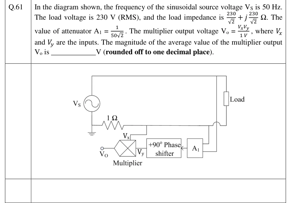
In the diagram shown, the frequency of the sinusoidal source voltage is 50 Hz. The load voltage is 230 V (RMS), and the load impedance is . The value of attenuator . The multiplier output voltage , where and are the inputs. The magnitude of the average value of the multiplier output is ________ V (rounded off to one decimal place).
 Tap to open full size
Figure description
A sinusoidal source V_S on the left. Its top terminal connects by a long top wire to the upper terminal of a box labelled 'Load' on the right. Its bottom terminal is grounded and also connects to the left end of a 1 Ω resistor drawn horizontally. The right end of the 1 Ω resistor continues as a horizontal wire that (a) has a tap going down to the V_x input of a multiplier (a box with an X in it) and (b) continues right, hopping over (not connecting to) a vertical wire, to the lower terminal of the Load. So the 1 Ω resistor is in series with the Load and carries the load current. An attenuator block A_1 has two input leads on its right: the upper lead connects to the horizontal wire at the load's lower terminal, the lower lead runs up the vertical wire (the one the horizontal wire hops over) to the top wire at the load's upper terminal; A_1 therefore senses the load voltage. The output of A_1 (arrow pointing left) feeds a block labelled '+90° Phase shifter', whose output is the V_y input of the multiplier. The multiplier output terminal on the left is labelled V_o.