
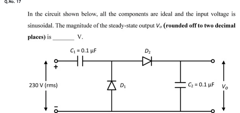
In the circuit shown below, all the components are ideal and the input voltage is sinusoidal. The magnitude of the steady-state output (rounded off to two decimal places) is ______ V.
 Tap to open full size
Figure description
A two-stage diode-capacitor circuit (a half-wave voltage doubler). On the left are two open input terminals: the upper one is marked + and the lower one is marked -. A double-headed vertical arrow between them is labelled 230 V (rms). The lower input terminal feeds the common ground rail. The upper input terminal connects through series capacitor C1 = 0.1 uF to a middle node. Diode D1 is vertical between the ground rail and the middle node, with its anode at ground and its cathode (bar) at the middle node, so its triangle points up. Diode D2 runs from the middle node toward the output, with its anode at the middle node and its cathode toward the upper output terminal, so its triangle points right. Capacitor C2 = 0.1 uF connects the output node to the ground rail. The output V_o is taken across C2, between two open output terminals (upper and lower), and is marked with a double-headed vertical arrow.