
IAE Academy

GATE 2022 IN Q.36: solution and answer

GATE 2022 · INQ.36 · 2 marks · MCQ

A signal shown is applied from ms to ms to the circuit shown. Given the initial voltage across the capacitor is 0.3 V, and that the diode is ideal, the open circuit voltage at ms is ________
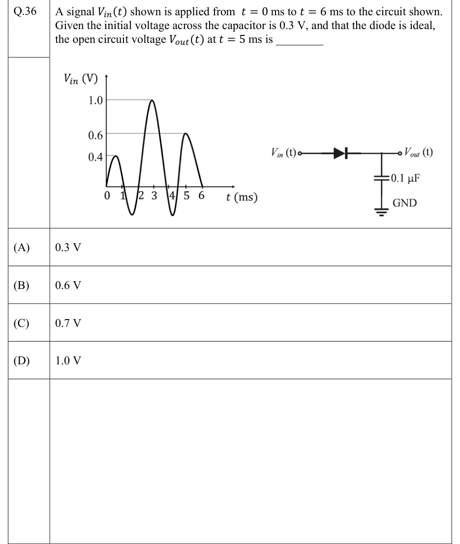
GATE 2022 IN question 36: Left: plot of V_in (V) against t (ms).Tap to open full size
Figure from the GATE 2022 IN paper. It is part of the question.
Figure description

Left: plot of V_in (V) against t (ms). The time axis has ticks at t = 0, 1, 2, 3, 4, 5, 6 ms. Dotted horizontal reference lines run from the vertical axis at 0.4, 0.6 and 1.0 V, and each one ends at a peak of the waveform. The waveform starts at 0 V at t = 0 and rises to a positive peak of 0.4 V at about t = 0.5 ms. It crosses zero just after t = 1 ms and dips to an unlabelled negative minimum at about t = 1.5 ms. It crosses zero again just before t = 2 ms and rises to the largest peak, 1.0 V, just before t = 3 ms. It crosses zero at about t = 3.8 ms and dips to a second unlabelled negative minimum, drawn to the same depth as the first, at about t = 4.2 ms. It crosses zero at about t = 4.5 ms, reaches its last positive peak, 0.6 V, at t = 5 ms, and falls back to 0 V at t = 6 ms, where the curve ends. Right: circuit. The input terminal V_in(t) connects to the anode of a series diode pointing from input to output. The cathode connects to the output terminal V_out(t) and to one plate of a 0.1 µF capacitor. The capacitor's other plate goes to ground (GND). Nothing else is connected to the output (open circuit).

  1. (A)

    0.3 V

  2. (B)

    0.6 V

  3. (C)

    0.7 V

  4. (D)

    1.0 V

Answer and solution

ANSWER

, option (D). The ideal peak detector charges to the largest input seen so far (1.0 V near t = 3 ms). With an open-circuit output it has no way to discharge, so it still holds 1.0 V while the input sits at its 0.6 V peak at t = 5 ms.

Official answer: DSource: Official answer key, GATE 2022 IN (IIT Kharagpur)

  1. Identify the circuit. An ideal diode in series with a shunt capacitor, and no load, is a positive peak detector (peak rectifier). Assume an ideal diode (zero forward drop, zero forward resistance, zero reverse current) and an ideal source. The output node is the capacitor's top plate, so at all times.

  2. When the diode conducts, the capacitor charges instantly. The diode conducts only while . There is no resistance in the charging path, so the charging time constant is zero and the capacitor follows the input exactly: . The value therefore plays no part.

  3. When the diode is off, the capacitor holds its voltage. When the diode is reverse biased and carries no current. The output is open circuit, so the capacitor has no discharge path, and the diode blocks any current that would pull it down. The capacitor can only charge upward, so

  4. First lobe, to about ms. peaks at , which is more than the initial . The diode turns on once passes , and the capacitor charges to at about ms. After that falls, the diode turns off, and is held through the first negative dip.

  5. Second lobe, peak just before ms. rises past (between 2 and 3 ms), so the diode turns on again and the capacitor follows the input up to the peak. Once falls below the diode turns off, and is held, including through the second negative dip near ms.

  6. At ms. The input is at its last peak, . The anode is at and the cathode at , so the diode is reverse biased by . It has not conducted since the peak, because over that whole interval. The capacitor is still at .

  7. Result. This is option (D).

KEY IDEA

A series ideal diode feeding a capacitor with no load is a peak detector. Its output is the largest of the initial capacitor voltage and every input value applied so far, . It is not the current input value. With no resistance in the loop, the size of does not matter.

WATCH OUT FOR

Choosing 0.6 V (B) by reading the input at t = 5 ms. The 0.6 V peak falls exactly at 5 ms, but the diode is reverse biased then because the capacitor is already at 1.0 V, and with an open-circuit output nothing discharges it. Other traps: keeping the initial 0.3 V (A) as if the input never exceeded it, and getting 0.7 V (C) by subtracting a silicon cut-in voltage or the initial 0.3 V from 1.0 V. The diode is ideal, so there is no drop, and the initial voltage only matters while the input stays below it.

From the GATE 2022 IN paper. Every question of this paper · Download the full paper · All 25 Diode circuits questions, with notes

More Diode circuits questions