
IAE Academy

GATE 2022 EC Q.57: solution and answer

GATE 2022 · ECQ.57 · 2 marks · NAT

A circuit and the characteristics of the diode (D) in it are shown. The ratio of the minimum to the maximum small signal voltage gain is ________ (rounded off to two decimal places).
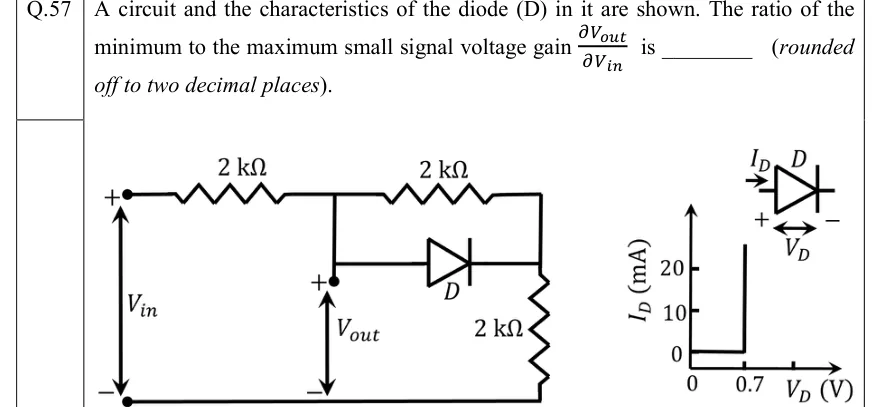
GATE 2022 EC question 57: Circuit: the input source V_in (+ on top, − at the bottom ground rail) feeds a series 2 k Ω resistor to node A.Tap to open full size
Figure from the GATE 2022 EC paper. It is part of the question.
Figure description

Circuit: the input source V_in (+ on top, − at the bottom ground rail) feeds a series 2 k Ω resistor to node A. V_out is taken at node A with respect to the bottom ground rail (+ at A). From node A two parallel branches go to node B: an upper 2 k Ω resistor, and below it diode D with its anode at A and its cathode at B (the triangle points from A toward B). From node B a 2 k Ω resistor goes down to the ground rail. Diode characteristic (right): I_D in mA on the vertical axis (ticks at 0, 10, 20), V_D in V on the horizontal axis (ticks at 0 and 0.7). I_D = 0 for V_D < 0.7 V, and at V_D = 0.7 V the curve rises vertically (any current at a fixed 0.7 V). The inset symbol defines I_D as the current entering the anode and V_D as the anode-to-cathode voltage (+ at the anode).

Answer and solution

ANSWER

The ratio of the minimum to the maximum small-signal voltage gain is . The gain is with the diode ON and with it OFF.

Official answer: 0.70 to 0.80Source: Official answer key, GATE 2022 EC (IIT Kharagpur)

  1. Diode model from the characteristic. For , , so the diode is an open circuit and its small-signal resistance is . At the curve is vertical: the voltage stays at 0.7 V whatever the current, so . For small signals it is a short.

  2. Circuit structure. drives a series resistor to node A, where is taken. Between A and B the second resistor sits in parallel with D (anode at A). A third resistor runs from B to ground. So is the voltage across ( D) in series with the bottom .

  3. Diode OFF. With the same current flows through all three resistors. By voltage division This holds while , i.e. for . That range includes every negative , where D is reverse biased.

  4. Diode ON (). Now D holds . All the current entering A through the series resistor reaches B, through the upper resistor or through D, and then flows through the bottom resistor. So Consistency check: for , so the diode is indeed conducting.

  5. Small-signal gain with the diode ON. From , The same result follows directly from the small-signal model: shorts the parallel pair, leaving the divider . The constant 0.7 V only shifts the operating point and adds nothing to the incremental gain.

  6. Ratio of minimum to maximum gain. The gain is in one region and in the other, so

KEY IDEA

With a piecewise-linear diode, the small-signal gain is constant within each region. Below 0.7 V the diode is an open (). On the vertical part of the curve it is a short (). Each case reduces to a plain resistive divider. The fixed 0.7 V drop only sets where the diode switches (at ) and has no effect on either gain.

WATCH OUT FOR

Taking at node B (across the bottom resistor only) gives gains and and a ratio of 0.67, which is outside the key. The printed terminal is at node A, the diode's anode. Other slips are inverting the ratio (max/min = 1.33), or letting the 0.7 V drop enter the incremental gain when it only shifts the operating point.

From the GATE 2022 EC paper. Every question of this paper · Download the full paper · All 25 Diode circuits questions, with notes

More Diode circuits questions