
IAE Academy

GATE 2023 EC Q.40: solution and answer

GATE 2023 · ECQ.40 · 2 marks · MCQ

In the circuit shown below, and are silicon diodes with cut-in voltage of 0.7 V. and are input and output voltages in volts. The transfer characteristic is
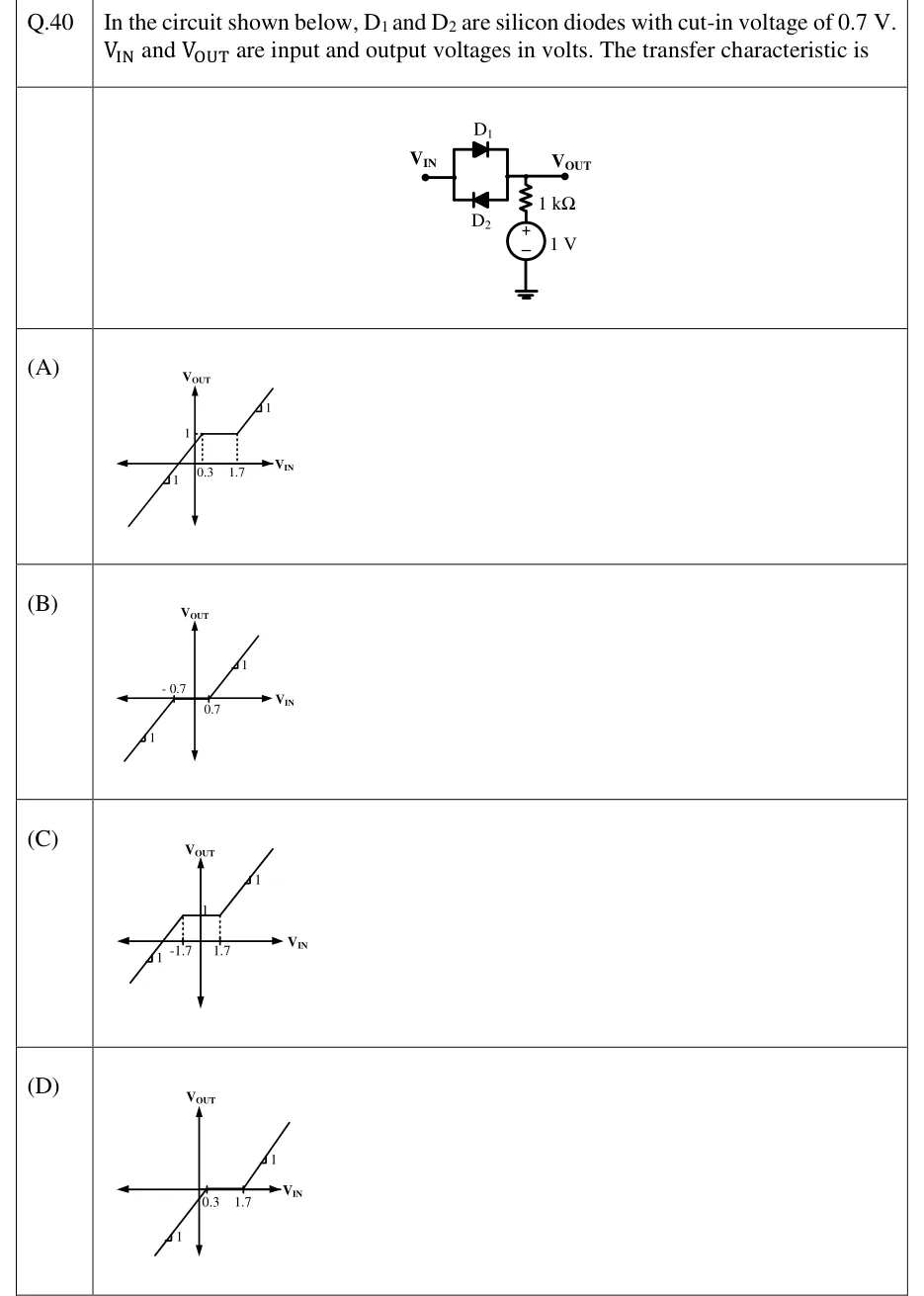
GATE 2023 EC question 40: Input terminal V_IN on the left.Tap to open full size
Figure from the GATE 2023 EC paper. It is part of the question.
Figure description

Input terminal V_IN on the left. Between V_IN and the output node V_OUT are two diodes in antiparallel. D1 (top branch) has its anode at V_IN and its cathode at V_OUT, so it conducts from V_IN to V_OUT. D2 (bottom branch) has its anode at V_OUT and its cathode at V_IN, so it conducts from V_OUT to V_IN. From the V_OUT node, a 1 kΩ resistor goes down to the + terminal of a 1 V DC source. The source's − terminal goes to ground. Nothing else is connected to V_OUT, so the output is open-circuited.

  1. (A)

    Figure: V_OUT vs V_IN. V_OUT is flat at 1 for 0.3 ≤ V_IN ≤ 1.7 (dotted verticals drop from the flat section to V_IN = 0.3 and V_IN = 1.7). For V_IN > 1.7 it rises with slope 1. For V_IN < 0.3 it falls with slope 1 and crosses the V_IN axis at a negative V_IN.

  2. (B)

    Figure: V_OUT vs V_IN. V_OUT = 0 for −0.7 ≤ V_IN ≤ 0.7 (a dead zone on the V_IN axis). Outside that range it is a line of slope 1: rising for V_IN > 0.7 and falling below zero for V_IN < −0.7.

  3. (C)

    Figure: V_OUT vs V_IN. V_OUT is flat at 1 for −1.7 ≤ V_IN ≤ 1.7 (dotted verticals at −1.7 and 1.7). Outside that range it is a line of slope 1: rising for V_IN > 1.7 and falling for V_IN < −1.7.

  4. (D)

    Figure: V_OUT vs V_IN. V_OUT = 0 for 0.3 ≤ V_IN ≤ 1.7 (a flat segment on the V_IN axis). For V_IN > 1.7 it rises with slope 1. For V_IN < 0.3 it falls below zero with slope 1.

Answer and solution

ANSWER

The transfer characteristic is option (A). stays at for , follows above ( on) and below ( on).

Official answer: ASource: Official answer key, GATE 2023 EC (IIT Kanpur)

  1. Model and assumptions: is driven by an ideal voltage source. Each diode uses the constant-voltage-drop model: it is off until its forward voltage reaches the cut-in value of , and after that it holds a constant drop with no series resistance. The output is open-circuited, so any current through the diodes must also flow in the resistor.

  2. Both diodes off: no current flows in the resistor, so there is no drop across it and (the source voltage).

  3. (anode at , cathode at ) turns on when . With this means . While it conducts, KVL across gives , a line of slope 1. Consistency check: the current from down through the resistor is , which is forward current in , as required.

  4. (anode at , cathode at ) turns on when . With this means . While it conducts, , again a line of slope 1. Consistency check: the current from the source up through the resistor into is , which is forward current in .

  5. The two diodes are antiparallel, so they never conduct at the same time. The complete characteristic is

  6. Check: the pieces meet at the breakpoints ( and ), so the curve is continuous. At , , so the lower line crosses the axis at , to the left of the origin. This is option (A): flat at between and , with slope 1 on both sides.

KEY IDEA

With both diodes off, no current flows in the resistor, so the output sits at the source voltage, not at . Each diode switches on once is away from that level: at and at . The result is a flat segment centred on , with the output following the input at unit slope on either side.

WATCH OUT FOR

Measuring the diode thresholds from instead of from the bias. That gives a dead zone of around the origin (option B) or a flat region at (option C). The other trap is taking while both diodes are off (option D). With no current in the resistor, the output equals the source voltage, .

From the GATE 2023 EC paper. Every question of this paper · Download the full paper · All 25 Diode circuits questions, with notes

More Diode circuits questions