
IAE Academy

GATE 2025 EC Q.34: solution and answer

GATE 2025 · ECQ.34 · 1 mark · NAT

All the components in the bandpass filter given below are ideal. The lower dB frequency of the filter is 1 MHz.

The upper dB frequency (in MHz, rounded off to the nearest integer) is ________.
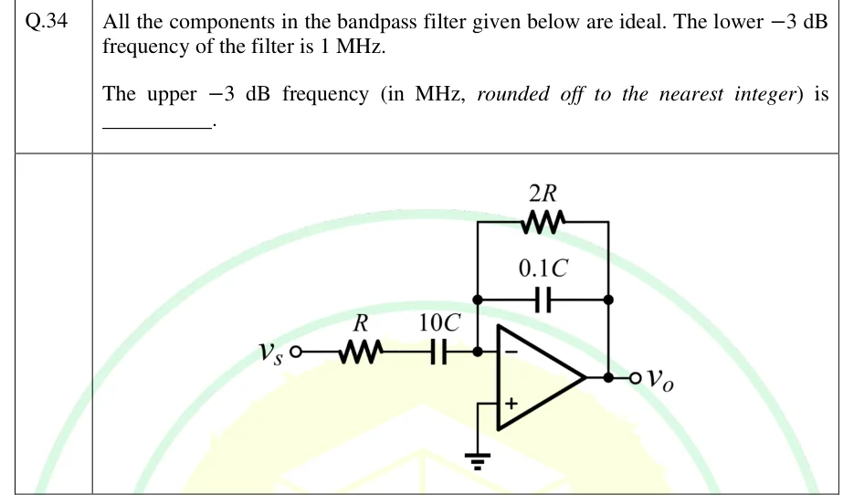
GATE 2025 EC question 34: Inverting op-amp bandpass filter.Tap to open full size
Figure from the GATE 2025 EC paper. It is part of the question.
Figure description

Inverting op-amp bandpass filter. The source v_s drives a series resistor R, which feeds a series capacitor 10C, and that capacitor connects to the op-amp's inverting (−) input. The non-inverting (+) input is grounded. The feedback network runs from the output v_o back to the inverting input and is a resistor 2R in parallel with a capacitor 0.1C. The output node is labelled v_o. No supply rails are drawn.

Answer and solution

ANSWER

The upper -3 dB frequency is 50 MHz (49.96 MHz before rounding), measured 3 dB below the midband gain of 2.

Official answer: 50Source: Official answer key, GATE 2025 EC (IIT Roorkee)

  1. Assume an ideal op-amp. The non-inverting input is grounded, so the virtual short holds the inverting input at virtual ground and no current enters the op-amp. The circuit is an inverting amplifier: , with and .

  2. Substitute the impedances. and , so

    The input network (, ) is a high-pass section with corner . The feedback network (, ) is a low-pass section with corner .

  3. Midband gain. Between the two corners, acts as a short and acts as an open, so and the midband gain is . The lower and upper dB frequencies are where the gain falls dB below , which means .

  4. Normalise the frequency. Put . Then and , so

  5. Apply the dB condition :

  6. Solve the quadratic in :

    This gives and , so and . The product of the roots is , so .

  7. Ratio of the band edges. Since ,

    The lower edge sits at , almost exactly on the lower corner, and the upper edge sits at , almost exactly on the upper corner, because the two corners are a factor of apart.

  8. Put in the data. With , . Rounded to the nearest integer, .

  9. Note on the reference level. Because the corners are only a factor of apart, the gain actually peaks at with value , a little below . If dB is measured from that peak instead of from the midband gain, the edges spread out to . The official key, , measures from the midband gain , which is the usual reference for an amplifier or filter whose band is set by separate low- and high-frequency corner networks.

KEY IDEA

The input network (R in series with 10C) is a high-pass section with corner 1/(2π·10RC). The feedback network (2R in parallel with 0.1C) is a low-pass section with corner 1/(2π·0.2RC). The midband gain is -2R/R = -2. The -3 dB points, taken 3 dB below that midband gain, fall at 1.0004 and 49.98 times the lower corner. That makes f_H/f_L = 49.96, which is essentially the corner ratio 10RC/0.2RC = 50, so f_H is about 50 MHz.

WATCH OUT FOR

Measuring -3 dB from the actual peak gain (about 1.96, at the geometric-mean frequency) instead of from the midband gain -2R/R = 2. That moves the band edges apart and gives 54 MHz, which is wrong. A second mistake is pairing the wrong components: using R with 0.1C, or 2R with 10C, for the corners gives the wrong ratio (100 or 25 instead of 50).

From the GATE 2025 EC paper. Every question of this paper · Download the full paper · All 13 Filters & waveforms questions, with notes

More Filters & waveforms questions