
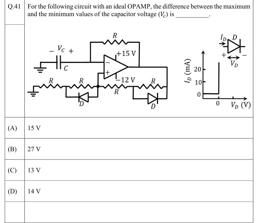
For the following circuit with an ideal OPAMP, the difference between the maximum and the minimum values of the capacitor voltage () is ________.
 Tap to open full size
Figure description
An ideal op-amp with supply rails +15 V (top) and −12 V (bottom). Inverting (−) input: connected to one plate of capacitor C, whose other plate is grounded. The capacitor voltage is labelled V_C in the figure (V_c in the stem; the same quantity), with − on the ground side and + on the op-amp side, so V_C is the voltage at the inverting input. A resistor R runs from the op-amp output back to the inverting input, a negative-feedback path to the capacitor. Non-inverting (+) input: connected to node P (marked with a dot) on a horizontal resistor ladder between ground and the output. From left to right: ground, resistor R, node A, resistor R, node P, resistor R, node B, resistor R, then the op-amp output. A diode D sits across the A–P resistor with its anode at P and its cathode (bar) at A, so it conducts from P to A. A second diode D sits across the B–output resistor with its anode at B and its cathode (bar) at the output end, so it conducts from B to the output. A separate graph gives the diode characteristic, I_D (mA) against V_D (V), with an inset diode symbol: I_D enters the anode, and V_D is measured + at the anode to − at the cathode. The current is zero for V_D < 0 and rises vertically at V_D = 0. The I_D axis has ticks at 0, 10 and 20 mA; the V_D axis has a labelled tick at 0 and an unlabelled tick to its right. So the diode is ideal, with 0 V cut-in and zero on-resistance.
- (A)
15 V
- (B)
27 V
- (C)
13 V
- (D)
14 V