
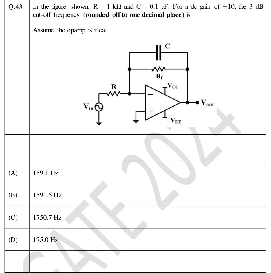
In the figure shown, and . For a dc gain of , the 3 dB cut-off frequency (rounded off to one decimal place) is
Assume the opamp is ideal.
 Tap to open full size
Figure description
Inverting op-amp low-pass (integrator-type) filter. The source V_in (bottom terminal grounded) connects through resistor R to the inverting (−) input of the op-amp. The feedback network between the inverting input and the output node is a resistor R_f in parallel with a capacitor C (C drawn above R_f). The non-inverting (+) input is grounded. The op-amp is powered by V_CC (top) and -V_EE (bottom). The output node is labelled V_out.
- (A)
159.1 Hz
- (B)
1591.5 Hz
- (C)
1750.7 Hz
- (D)
175.0 Hz