
IAE Academy

GATE 2026 EC Q.17: solution and answer

GATE 2026 · ECQ.17 · 1 mark · MCQ

The ideal OP-AMP circuit shown in the Figure produces output voltage when the Switch, S, is open.

Which of the options represents the output voltage when S is closed?
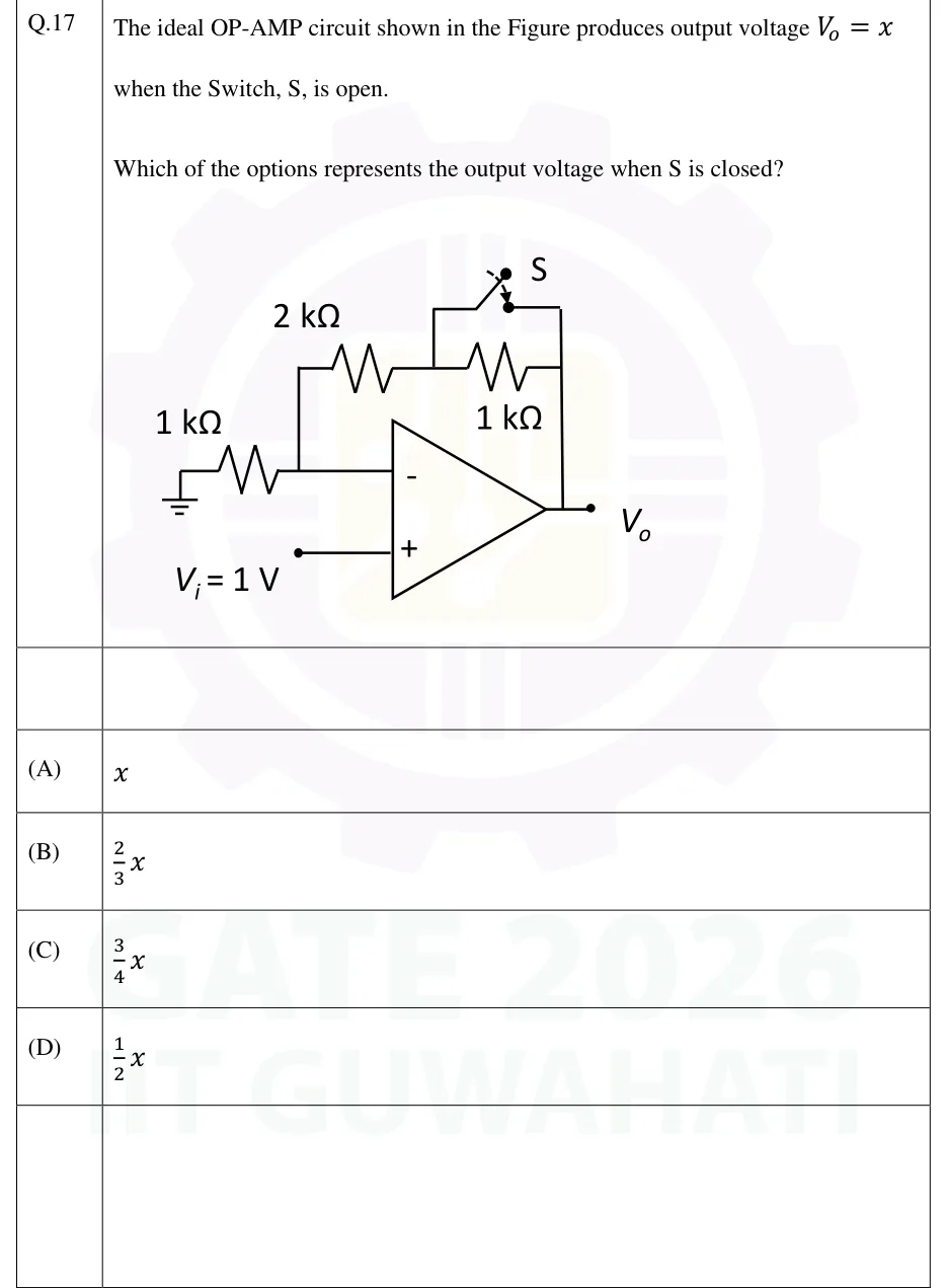
GATE 2026 EC question 17: Non-inverting amplifier using an ideal op-amp.Tap to open full size
Figure from the GATE 2026 EC paper. It is part of the question.
Figure description

Non-inverting amplifier using an ideal op-amp. The non-inverting (+) input is driven by a source V_i = 1 V. The inverting (-) input node connects to ground through a 1 k Ω resistor. The feedback path from the inverting node to the output V_o is a 2 k Ω resistor in series with a 1 k Ω resistor (the 2 k Ω is on the inverting-node side, the 1 k Ω on the output side). A switch S is connected from the junction between the 2 k Ω and the 1 k Ω feedback resistors directly to the output line, i.e. S is in parallel with the 1 k Ω feedback resistor. S is drawn open. The output terminal is labelled V_o.

  1. (A)

  2. (B)

  3. (C)

  4. (D)

Answer and solution

ANSWER

When S is closed the output voltage is (it falls from 4 V to 3 V). The answer is (C).

Official answer: CSource: Official answer key, GATE 2026 EC (IIT Guwahati)

  1. Assume an ideal op-amp: the virtual short gives , and no current flows into either input. The circuit is a non-inverting amplifier with from the inverting node to ground and a feedback resistance from the inverting node to the output.

  2. KCL at the inverting node: the current through is and all of it flows through , so . This gives the non-inverting gain

  3. S open: the feedback path is the resistor in series with the resistor, so and

  4. S closed: S is wired from the junction of the two feedback resistors straight to the output, which puts it across the output-side resistor. Closing it shorts that resistor, leaving .

  5. Output with S closed:

  6. Ratio: , so . This is option (C).

KEY IDEA

For an ideal non-inverting amplifier, . Closing S shorts the feedback resistor, so drops from to and the gain drops from 4 to 3. The ratio of the two outputs is the ratio of the two gains, .

WATCH OUT FOR

Taking the ratio of the feedback resistances (, option B) instead of the ratio of the gains. A non-inverting gain is , not , so the '1 +' term has to be kept. Another slip is using the inverting-amplifier formula , which also gives for the ratio.

From the GATE 2026 EC paper. Every question of this paper · Download the full paper · All 36 Op-amps questions, with notes

More Op-amps questions