
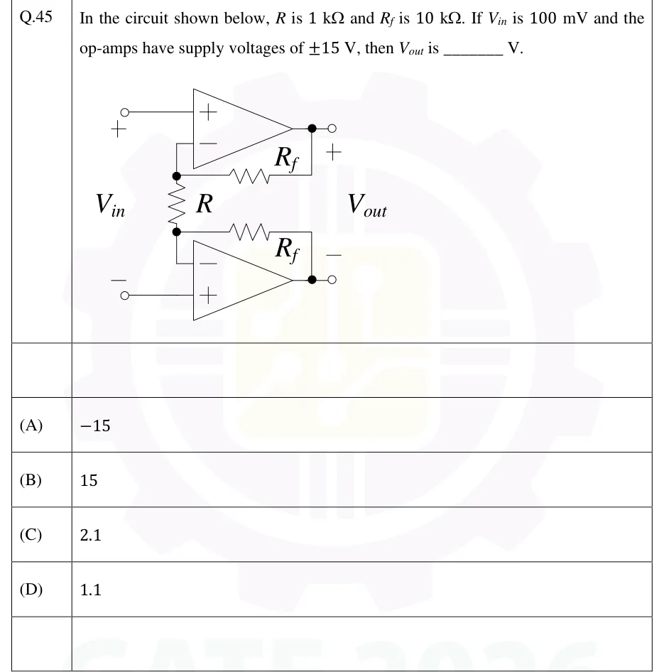
In the circuit shown below, is and is . If is and the op-amps have supply voltages of , then is ________ V.
 Tap to open full size
Figure description
Two op-amps, one above the other: the input stage of an instrumentation amplifier. Top op-amp: its non-inverting (+) input goes straight to the '+' terminal of the input V_in (upper left open terminal). Its inverting (−) input connects to a node at the top end of resistor R. A feedback resistor R_f runs from that node to the top op-amp's output, which is the upper output terminal, marked '+'. Resistor R runs vertically between the top node and a bottom node. Bottom op-amp: its inverting (−) input connects to the bottom node of R. A second feedback resistor R_f runs from the bottom node to the bottom op-amp's output, which is the lower output terminal, marked '−'. Its non-inverting (+) input goes straight to the '−' terminal of the input V_in (lower left open terminal). V_in is applied between the upper-left (+) and lower-left (−) terminals. V_out is taken between the two op-amp outputs (+ at the top output, − at the bottom output). Both op-amps run from ±15 V supplies.
- (A)
- (B)
- (C)
- (D)