
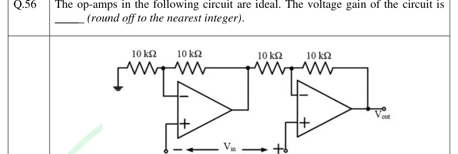
The op-amps in the following circuit are ideal. The voltage gain of the circuit is ______ (round off to the nearest integer).
 Tap to open full size
Figure description
Two ideal op-amps in cascade (a two-op-amp instrumentation/difference amplifier). Op-amp 1 (left): its inverting (−) input connects to the junction of two 10 kΩ resistors in series along the top; the left 10 kΩ goes from that junction to ground, the right 10 kΩ goes from that junction to the output of op-amp 1 (feedback). The non-inverting (+) input of op-amp 1 goes down to an open terminal marked '−' of the input voltage V_in. Op-amp 2 (right): the output of op-amp 1 connects through a 10 kΩ resistor to the junction at the inverting (−) input of op-amp 2, and a second 10 kΩ resistor goes from that junction to the output of op-amp 2 (feedback). The output of op-amp 2 is V_out. The non-inverting (+) input of op-amp 2 goes down to an open terminal marked '+' of V_in. V_in is drawn as a double-headed arrow between the '−' terminal (op-amp 1 + input) and the '+' terminal (op-amp 2 + input). All four resistors are 10 kΩ.