
IAE Academy

GATE 2024 IN Q.29: solution and answer

GATE 2024 · INQ.29 · 1 mark · NAT

Consider the readout circuit of a piezoelectric sensor shown in the figure.

When the piezoelectric sensor generates a charge , the resulting change in voltage is V. Then the corresponding change in the voltage is ______ V (rounded off to nearest integer).

Note: Assume all components are ideal.
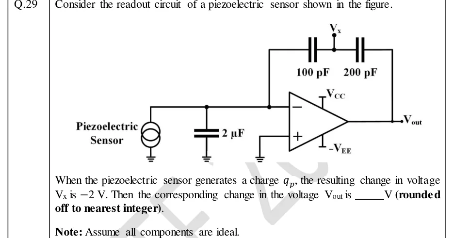
GATE 2024 IN question 29: A charge-amplifier readout circuit.Tap to open full size
Figure from the GATE 2024 IN paper. It is part of the question.
Figure description

A charge-amplifier readout circuit. On the left, the piezoelectric sensor is drawn as a current source (two overlapping circles) with its bottom terminal grounded and its top terminal on a horizontal wire. A 2 µF capacitor goes from that same wire to ground. The wire continues to the inverting (−) input of an op-amp. The op-amp's non-inverting (+) input is grounded. Its supplies are +V_CC (top) and −V_EE (bottom), and its output node is labelled V_out. The feedback path from the inverting input to V_out is two capacitors in series: 100 pF next to the inverting input, then 200 pF next to the output. The node between the two capacitors is brought out as terminal V_x.

Answer and solution

ANSWER

The change in is .

Official answer: -3Source: Official answer key, GATE 2024 IN (IISc Bengaluru)

  1. Assumptions: the op-amp is ideal (infinite open-loop gain, zero input current), and nothing loads the node , so no current leaves it. All voltages and charges below are changes caused by the sensor charge .

  2. Virtual short at the op-amp inputs: the input is grounded, so and negative feedback forces . The capacitor from the inverting node to ground therefore has across it and takes no charge. It does not affect the result.

  3. Charge conservation at the inverting node: no current enters the op-amp and none goes into the capacitor, so all of goes into the feedback branch. The and capacitors are in series and nothing is drawn from , so each one carries the same charge .

  4. Charge on the 100 pF capacitor (): the voltage across it is , so

  5. Same charge on the 200 pF capacitor ():

  6. Output: .

  7. Check using the series capacitance: , so The same result in one line: .

KEY IDEA

This is a charge amplifier. The virtual ground holds the inverting node at 0 V, so the sensor's shunt capacitance (2 µF) takes no charge and all of goes onto the feedback capacitors. Since nothing loads , the two series capacitors carry the same charge. So gives you through the 100 pF capacitor, and then gives you the extra drop across the 200 pF capacitor.

WATCH OUT FOR

Taking as the output, or splitting the voltage the wrong way. With equal charge, the drop across each series capacitor goes as , so the 200 pF capacitor drops half as much as the 100 pF one (1 V, not 4 V). Another mistake is letting the 2 µF sensor capacitance share the charge. It sits at virtual ground and takes none.

From the GATE 2024 IN paper. Every question of this paper · Download the full paper · All 36 Op-amps questions, with notes

More Op-amps questions