
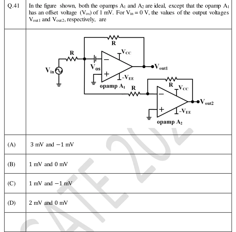
In the figure shown, both the opamps and are ideal, except that the opamp has an offset voltage () of 1 mV. For V, the values of the output voltages and , respectively, are
 Tap to open full size
Figure description
Two op-amps, A1 (upper) and A2 (lower), each powered by +V_CC and -V_EE. Source V_in (sinusoidal symbol, lower terminal grounded) feeds a resistor R into a node X. From node X: a feedback resistor R goes to V_out1 (output of A1); a battery V_os is in series between node X and the inverting (-) input of A1, drawn with its long plate (positive terminal) on the node X side and its short plate (negative terminal) on the op-amp's inverting input side; the non-inverting (+) input of A1 is grounded. Node X also connects, through another resistor R, to the inverting (-) input of A2; A2 has a feedback resistor R from its output V_out2 to its inverting input, and its non-inverting (+) input is grounded. All four resistors are equal to R.
- (A)
3 mV and −1 mV
- (B)
1 mV and 0 mV
- (C)
1 mV and −1 mV
- (D)
2 mV and 0 mV