
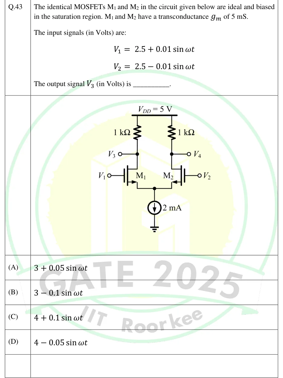
The identical MOSFETs M and M in the circuit given below are ideal and biased in the saturation region. M and M have a transconductance of 5 mS.
The input signals (in Volts) are:
The output signal (in Volts) is ________.
 Tap to open full size
Figure description
NMOS differential pair. Supply rail V_DD = 5 V at the top. Two 1 kΩ drain resistors hang from V_DD: the left one to the drain of M1, the right one to the drain of M2. The drain node of M1 is brought out as output V3 (terminal on the left); the drain node of M2 is brought out as output V4 (terminal on the right). M1 (n-channel enhancement MOSFET, arrow on the source) has its gate driven by input V1 from the left; M2 (identical n-channel MOSFET) has its gate driven by input V2 from the right. The sources of M1 and M2 are tied together at a common node, which connects to an ideal DC current source of 2 mA pointing downward (current flowing from the common source node to ground), whose lower terminal is grounded.
- (A)
- (B)
- (C)
- (D)