
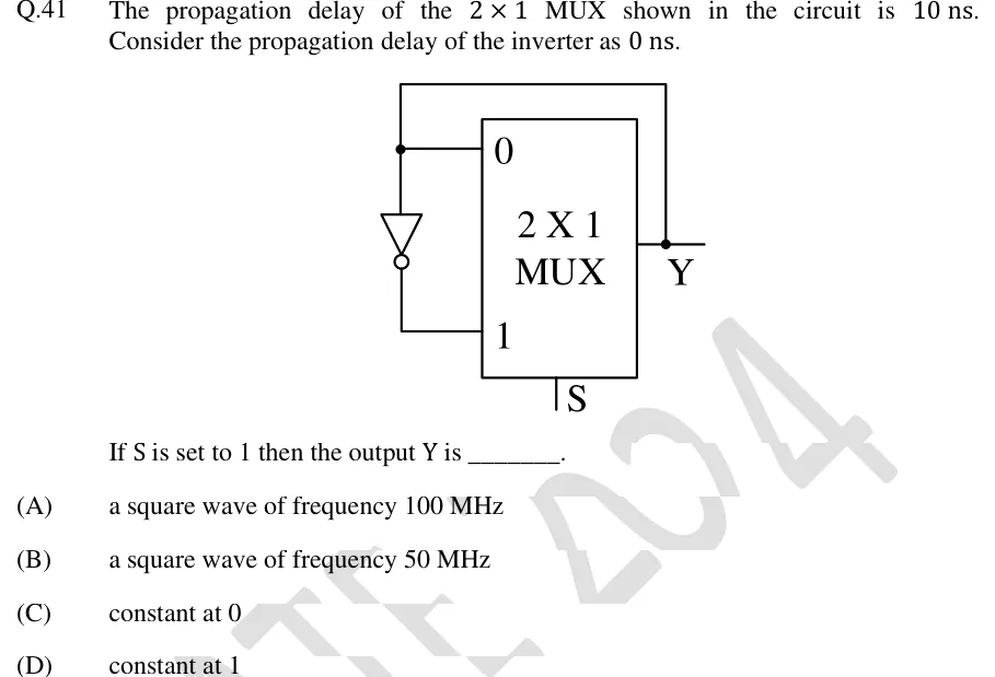
The propagation delay of the MUX shown in the circuit is . Consider the propagation delay of the inverter as .
[Figure]
If S is set to 1 then the output Y is ________.
 Tap to open full size
Figure description
A 2 X 1 MUX block with data inputs labelled 0 (upper) and 1 (lower), select input S at the bottom, and output Y on the right. From the output Y a junction dot leads a wire up above the MUX, left across the top and down to a junction dot on the line entering input 0, so input 0 is wired directly to Y. From that same junction dot an inverter (triangle pointing downwards with the bubble at its lower end) runs down, and its output goes right into input 1. So I0 = Y and I1 = Y' (complement of Y). Propagation delay: MUX 10 ns, inverter 0 ns.
- (A)
a square wave of frequency 100 MHz
- (B)
a square wave of frequency 50 MHz
- (C)
constant at 0
- (D)
constant at 1